Locomotives -
Operational Locos -
Locos under overhaul -
Locos on static display -
Locos formerly based on the Bluebell
Loco Roster -
Loco Stock List -
Loco Works News -
Join the Loco Dept


Bluebell Railway Villa Team
Repair of Birch Grove's boiler
The boiler work was undertaken between 1994 and 1998.
Funding from the late Bernard Wright's legacy enabled the Bluebell to employ contract boilersmiths for some of the work.
On the remaining old outer wrapper plates there was considerable corrosion around
a number of stay heads.
These were repaired by fitting screwed-in ferrules which were then seal-welded,
and drilled to the stay size.
![[View of wasted plate aroung stay heads]](976_010_tn.jpg)
Wastage around the stay heads.
The numbers are the lengths of new stays required.
|
![[View of new ferrules for stays]](976_009_tn.jpg)
Some of the new ferrules for the stays.
The large hole is for a washout plug.
|
Whilst the inner firebox was out the opportunity was taken to needle-gun the inside of
the outer wrapper plates and the barrel plates.
Having done this it was obvious that the front tubeplate was wasted around the flange
and needed replacing.
A blank plate was obtained;
in the workshop the flange was welded on,
and the holes for the tubes plugs and pipes were drilled.
The new tubeplate was fitted into the barrel front,
with the holes for the rivets drilled in situ,
and rivetted in.
The new outer wrapper plates were clamped in position with the foundation ring and
formed at the edges where they meet.
The new plates were then welded to the old ones where thay had been cut off.
The copper inner firebox was then replaced and held in position by bolts through the
foundation ring so that the stay holes in the new outer wrapper plates could be
drilled by marking through from the holes in the inner firebox;
once a pilot hole was drilled,
the holes were drilled and reamed from the outside.
![[View of boiler with holes being drilled]](bn38_3_14ae_tn.jpg)
|
The two contract boilersmiths drilling holes for the front tubeplate rivets and the
firebox side stays.
|
|
The foundation ring and fire-hole ring have been rivetted using a new tool purchased
for the job which looks like a large G-clamp.
This uses hydraulic pressure to squeeze the rivet,
resulting in a tighter and more consistent fix than could be made by hand.
|
![[View of hydraulic rivetter]](982_010_ts.jpg)
|
![[View of front and side of firebox]](976_006_tn.jpg)
|
![[View of firebox backplate]](976_005_tn.jpg)
|
![[View of firehole ring]](976_008_tn.jpg)
|
|
The firebox side and throatplate,
with foundation ring rivetted and stay holes tapped.
The rivetting tool cannot reach the corners so these were done by hand.
|
The firebox backplate.
The two oval holes are for the mud-hole doors used for washing out the scale.
|
The firehole ring,
showing the new machine-fitted rivets.
|
![[View of stay hole being tapped]](978_001_hs.jpg)
|
Fitting of the new side stays in progress.
Threads were re-cut in all 614 holes by driving a 15-in long tap right through using
an air spanner - the picture shows Neil Fuller tapping one of the holes.
The original stays had been 1in diameter,
but over the years many had been replaced by 1.1/8in;
all the holes have been reamed to this larger size so that a single size of
stay can be used.
Where the old stays were this larger size the copper-side threads were re-used by
tapping from the inside,
with the other holes tapped from the outside.
The new stays,
made of arsenical copper,
were made by fastener manufacturer.
They are of ten different lengths,
varying from 4 3/4in to 7 1/2in.
|
![[View of stays laid out in size order]](976_003_tn.jpg)
|
![[Close-up of a stay]](976_004_tn.jpg)
|
|
The stays laid out in their various lengths.
|
Close-up of a new stay,
showing the two threaded ends which screw into the plates and the plain middle.
|
Stays are fitted by gripping one end in a stud box,
and screwing them into the threaded holes so that 3/8in is left sticking out each
side;
the two threads are "in pitch" so that the stay screws right in as if it were a
continuous thread.
The middle part is made plain to help keep them free of scale.
A problem arose early in this operation when it was found that the stays had been
badly made,
and it was necessary to have a new batch made,
all of which have now been screwed into place.
The remaining job on these stays is to bead over the ends with a rivetting gun to
seal them against the plate and prevent them burning.
![[View of stay being fitted]](976_011_tn.jpg)
|
Neil Fuller winding in a new stay.
|
|
The firebox inside,
seen as the boiler stands upside-down.
On the left some stays are in position;
along the front seam can be seen the new rivets;
the four spigots are for supporting the brick arch.
The extensive pitting of the copper plate is thought to be due to the use of
Kent coal in the 1960s.
|
![[View inside firebox]](978_005_hs.jpg)
|
![[View of stays knobbled over]](979_014_hs.jpg)
|
Andrew Wilkens working on knobbling-over the exposed ends of the side stays.
Those already knobbled over show up as a bright shiny copper colour.
Click
here
for full details of this job.
|
![[View of the firebox crown]](97a_014_hs.jpg)
|
This picture shows the firebox crown,
looking directly down the left side;
the bracket in the centre bolts to the left tank
(and shows evidence of a number of different fixings in the past).
The washout-plug pad on the left was removed to change wasted nuts and studs.
The bright rings lower down are the holes for the crown stays.
|
|
A crown-stay hole,
showing how our contract boilersmiths are re-making the holes by building up
the inside of the hole with arc-welding,
which will then be reamed out and re-tapped to the original size,
using a tap which is being made for the job.
|
![[View of a firebox crown-stay hole]](97a_013_hs.jpg)
|
![[View of the firebox crown outside]](97b_002_hs.jpg)
|
The 80 crown stays are now fitted.
These steel stays have been made in the workshop.
On their outside ends they are knobbled over in the same way as the copper
side stays.
|
|
A crown stay are being knobbled over in the same way as the copper side stays.
|
![[View of a knobbled-over crown stay]](97c_002_hs.jpg)
|
![[View of the firebox crown inside]](97b_003_hs.jpg)
|
A view inside the firebox showing the newly-installed crown stays.
On the inside end these will be fitted with nuts.
The two rows of nuts nearest the tubeplate are for the bridge pieces which
support the front of the crown (see next picture).
|
|
A view inside the boiler barrel looking back over the firebox crown.
The shiny vertical bars are the new crown stays.
The curved red-painted pieces in the foreground are the bridge pieces which
support the front of the crown sheet,
with the front (slightly thicker) row of stays passing through them.
The long bars still covered in scale are the logitudinal stays running from the
front tubeplate to the firebox backplate.
Rather out of focus at the top are the rivets holding the boiler barrel onto the
firebox outer crown sheet.
Just visible near the bottom are two of the rivets holding the inner crown
sheet to the front tubeplate.
|
![[View of the firebox crown from inside barrel]](97b_001_hs.jpg)
|
![[View of the front tubeplate]](97b_004_hs.jpg)
|
The front tubeplate
(viewed as the boiler lies on its right side).
The nuts are holding the logitudinal stays,
some of which are just visible through the tube holes;
the brown drips are Loctite used to help them stay put.
The large hole is the end of the main steam pipe,
which has had this end trimmed back to fresh copper by extending the other
end.
The studs are used to bolt on a cast steel elbow to which the copper main
steam pipe is fixed.
|
|
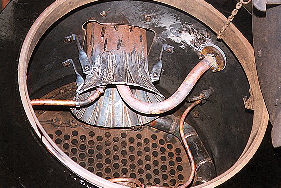
The other end of the main steam pipe inside the dome.
The regulator valve bolts onto the flange.
Visible inside the barrel are some logitudinal stays,
and the two pipes which take steam from the dome to the injector valves
mounted on the backplate.
|
![[View inside the dome]](97b_005_hs.jpg)
|
![[View of a backhead turret]](97c_001_hs.jpg)
|
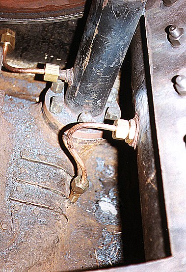
The two turrets on the boiler backhead on which the injector steam valves are
mounted have been installed.
These also have mounting points for the steam valves feeding the
Westinghouse pump,
the steam sanding gear,
and the train heating.
As they are hollow castings they have been installed now so that they can by
hydraulically tested with the boiler itself.
The four plain-headed fasteners visible around the studs for the injector
steam valve are countersunk set-screws fittes by shear-off heads.
|
|
Birch Grove's boiler is fitted with six bronze castings on the curved sides of
the firebox outer wrapper plate into which the washout plugs are screwed.
The central part was originally much longer and was closed with a cap,
in the style of many LSWR boilers,
which screwed down over an outside thread and was sealed with a copper ring.
During the time it was repaired at Ashford the central part was cut down and
fitted with a conventional tapered washout plug.
These castings were life-expired,
with years of having plugs tighened resulting in the central part being
swollen out
(some are worse than in this picture).
|
![[View of an old crown washout-plug pad]](97c_003_hs.jpg)
|
![[View of firebox crown washout plug pad castings]](981_011_qs.jpg)
|
New castings have been made,
which have a longer central part,
with a small tapered washout plug fitted,
leaving the wall thickness greater than it is now.
|
![[View of machining a firebox crown washout plug pad casting]](981_009_qs.jpg)
|
The pad castings need to be machined to fit the curved face of the firebox.
These pictures show the vertical borer being used to cut the curved face.
|
![[View of machining the firebox crown washout plug pad castings]](981_010_qs.jpg)
|
|
All the firebox crown washout plug pads have been fitted.
|
![[View of fitted firebox crown washout plug pad]](982_001_ts.jpg)
|
![[View of front tubeplate]](981_007_qs.jpg)
|
The front tubeplate with all the tubes expanded.
The smokebox will be fitted after the hydraulic test.
|
|
A small leak from one of the rivets fixing the firebox outer wrapper and throatplate to the barrel,
showing that it really does have water inside for the first time since 1971.
Leaks like this are to be expected after such major repairs and will be stopped by caulking techniques.
|
![[View of leaky rivet]](981_008_qs.jpg)
|
|
A close-up view of the safety valves,
fitted without the spring for the hydraulic test.
[Click on the image for full-size picture.]
|
![[View of assembled safety-valves]](982_002_ts.jpg)
|
![[View of the new ashpan under construction]](97a_011_hs.jpg)
|
The new ashpan is complete.
|
|
The new smokebox is complete.
The door and hinges are the only old parts re-used.
|
![[View of the new smokebox under construction]](97a_012_hs.jpg)
|
![[View of the chimney]](97b_006_hs.jpg)
|
The chimney,
standing upside-down,
showing a substantial crack which has now been welded.
The cap of the chimney casting is hollow with holes in its top face.
The crack was made by water freezing inside some time during the many years
it has stood around unused.
|
Inside the smokebox
The following views show the inside of the smokebox with all the pipes and
fittings in place but whilst it is still clean.
|
A general view looking into the smokebox,
showing how the smokebox wrapper plate is cut away at the bottom to give
access to the top of the cylinders.
|
|
A general view looking upwards towards the chimney base.
The petticoat pipe was replaced with a new one;
the narrow V shapes are where sections were welded in to make the splayed out
end.
The large pipe in the right foreground is the exhaust from the vacuum ejector,
whilst the smaller pipe on the left is that from the air pump.
The small pipe in the right background goes to the blower ring,
and the large black pipe is the main steam pipe.
Note also that the door ring has a rectangular slot into which a sealing strip
is fitted.
|
|
|
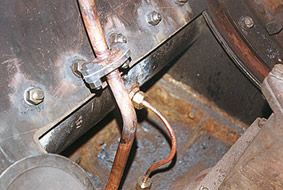
A view looking looking down onto the right side.
The larger pipe is the new air pump exhaust pipe,
fitted with a joint for easy maintenance just above the level of the
concrete which will form the floor.
The small pipe is from the Furness lubricator fitted on the side of the
smokebox saddle,
which feeds oil directly into the top of the cylinder.
|
|
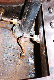
A view looking looking down onto the left side,
showing the pipe from the Furness lubricator going into the cylinder just
below the patch fitted over the corroded portion.
At the back is the main steam pipe with the small pipe fed from the
hydrostatic lubricator in the cab.
Note the use of bronze cap nuts on the main steam pipe studs.
|
|
|
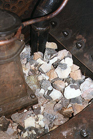
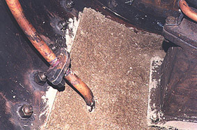
The space below the wrapper plate is filled with rubble
(actually broken bits of an old "brick-arch").
A layer of concrete has now been placed over this to form the floor of the
smokebox.
This protects the delicate small pipework and eases fireman's job of cleaning
out the ash.
|
|
Back to the Birch Grove overhaul page


Return to BRPS Home Page,
to the Timetable or to Special
Events
Locos Intro -
Operational Locos -
Locos under overhaul -
Locos on static display -
Locos formerly based on the Bluebell
Loco Roster -
Loco Stock List -
Loco Works News -
Join the Loco Dept
Visitor Info. -
Museum -
Trust -
Catering -
Contacts -
What's New -
Projects -
Locos -
Carriages & Wagons -
Signals -
History -
Other -
Links -
Search -
FAQ
Why not become a BRPS Member? -
Get more involved as a Volunteer
Your ideal Film/TV location?
 Last updated 7 July 1998 by Lewis Nodes, and recovered by Richard Salmon 30 September 2020, updated 27 February 2024.
© Copyright BRPS. Privacy Policy
|


![[View of wasted plate aroung stay heads]](976_010.jpg)
![[View of new ferrules for stays]](976_009.jpg)
![[View of boiler with holes being drilled]](bn38_3_14ae.jpg)
![[View of hydraulic rivetter]](982_010.jpg)
![[View of front and side of firebox]](976_006.jpg)
![[View of firebox backplate]](976_005.jpg)
![[View of firehole ring]](976_008.jpg)
![[View of stay hole being tapped]](978_001.jpg)
![[View of stays laid out in size order]](976_003.jpg)
![[Close-up of a stay]](976_004.jpg)
![[View of stay being fitted]](976_011.jpg)
![[View inside firebox]](978_005.jpg)
![[View of stays knobbled over]](979_014.jpg)
![[View of the firebox crown]](97a_014.jpg)
![[View of a firebox crown-stay hole]](97a_013.jpg)
![[View of the firebox crown outside]](97b_002.jpg)
![[View of a knobbled-over crown stay]](97c_002.jpg)
![[View of the firebox crown inside]](97b_003.jpg)
![[View of the firebox crown from inside barrel]](97b_001.jpg)
![[View of the front tubeplate]](97b_004.jpg)
![[View inside the dome]](97b_005.jpg)
![[View of a backhead turret]](97c_001.jpg)
![[View of an old crown washout-plug pad]](97c_003.jpg)
![[View of firebox crown washout plug pad castings]](981_011_2ts.jpg)
![[View of machining a firebox crown washout plug pad casting]](981_009_2ts.jpg)
![[View of machining the firebox crown washout plug pad castings]](981_010_2ts.jpg)
![[View of fitted firebox crown washout plug pad]](982_001.jpg)
![[View of front tubeplate]](981_007_2ts.jpg)
![[View of leaky rivet]](981_008_2ts.jpg)
![[View of assembled safety-valves]](982_002.jpg)
![[View of the new ashpan under construction]](97a_011.jpg)
![[View of the new smokebox under construction]](97a_012.jpg)
![[View of the chimney]](97b_006.jpg)