After a long gestation period plans were finally agreed for
renewal of the track layout at Horsted Keynes, obviously impinging on the
Signalbox.
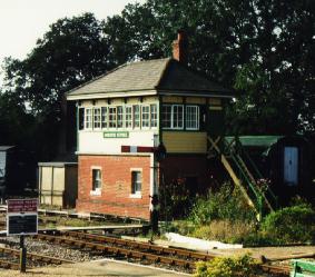
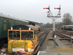
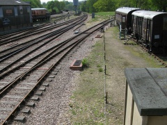
Left: Horsted Keynes Signalbox in the days before the work began. Photograph: Richard Salmon
The old arrangement had the former number three road up
starter and the point leading to numbers two and three roads controlled by a
ground frame which in turn was under the overall control of the signalman in
the box. This point did not have a lock for movements into the former number
three road, resulting in all down passenger trains having to use the then
number two road. Although the old numbers one and two roads do join north of
the station, at "Leamland Junction", this had not been an operational
route and trains could only enter or leave number one road from the south. We
now have bi-directional running on all roads, so the new changes included
making "Leamland Junction" operational and installing locking for
movements south into what was number three road. When all of this trackwork was
completed the points involved were then worked directly from the box.
Better signalling of the approach from the north (and at the
same time a move further up the line for the advanced starter) created a demand
for additional capacity on the signal box's frame. When considering as well
the plans for the change to the layout south of the station, forty levers on
their own appeared to be insufficient for our needs. Several ideas were put
forward to cope with this problem, only two of which were really practical.
The first was to build a replica, but bigger, box to replace the existing one
(whose structure was in sore need of repair), and the second to enlarge the
existing box whilst at the same time repairing it. 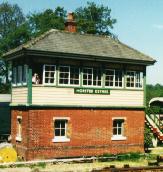 Neither of these
options was, however, available as early in 1997 someone applied for, and
obtained, a grade two listing for the whole Horsted Keynes station area,
especially mentioning the signal box. We could knock it down in the interests
of safety, but we could not modify its fabric in the slightest way!
Neither of these
options was, however, available as early in 1997 someone applied for, and
obtained, a grade two listing for the whole Horsted Keynes station area,
especially mentioning the signal box. We could knock it down in the interests
of safety, but we could not modify its fabric in the slightest way!
So, where to go next? It was decided to have some functions
operating remotely, as for the down distant signal at Sheffield Park. This
means quite a few power-worked points and signals, a move which was not very
popular but is, however, the best course of action and the one that is being
instigated.
Work Progress
By clicking on the images you will be taken to a larger version, which
may have more content than the smaller version on this page.
First Quarter 2014
At last! On Saturday, 11th January, the last signals (Nº26 Down Yard exit
and Nº24A from Nº4 road to down-yard) were transferred back to the frame which means all
the panel switches in the 'box have now disappeared.
The first movement to be signalled using this dummy was for a trolley that
needed to go to the Down Yard.
Nº24A in the off position. |
Trolley signalled into the Down Yard. |
Text and photographs: Jon Bowers
Third Quarter 2013
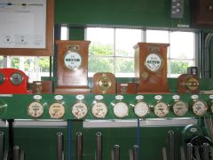
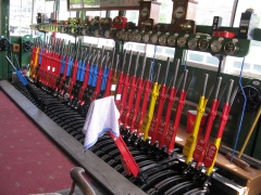
Nearly all functions originally controlled using temporary switches, have been
transferred to the lever frame. There are only three switches still in use and these will be
transfered to levers in the near future. There are additional functions that have not previously
been under the control of the signal box that also need to be connected to levers. The Long Section
Working (Sheffield Park - Kingscote) is also yet to be commissioned.
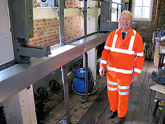
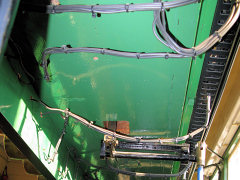
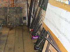
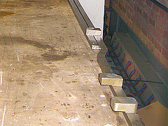
The signal box is presently undergoing remedial repairs to replace rotten
timbers and window frames. The pictures indicate the extent of the work.
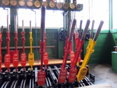
The last three switches. |
Signal levers pulled for a down train from Kingscote. |
Signal levers pulled for an up train from Sheffield Park. |
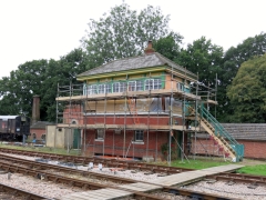
Horsted 'box under repair
Text and photographs: Chris Majer
Second Quarter 2013
All the signals have now been mechanically rehearsed to ensure correct
adjustment and ease of operation, in some cases the electric signal motors were temporary
disconnected but have now been reconnected until the appropriate electrical stages have been
completed. The relay room work has also progressed well with stage 14 now commissioned out of the
18 stages required for final completion. The Sykes Treadle Instruments have been brought (back)
into use at Horsted Keynes, applicable to the Up First Advance and Second Advance Starting Signals.
They were last in action before the resignalling work started and at that time applied to the Down
Starting Signals.
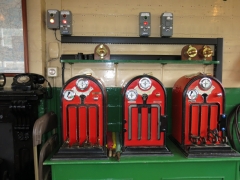
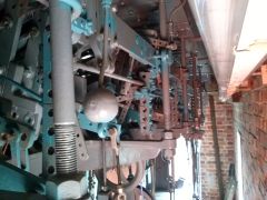
The photos are of the two instruments showing 'Free' for Up direction
routes towards Kingscote and the second picture shows the complex mechanical arrangement on the
underside of the lever frame.
The two Sykes Instruments. |
The complex mechanical arrangement on the
underside of the lever frame. |
| Photo: Chris Majer |
Photo: Brian Hymas |
Text: Chris Majer and Brian Hymas
Brian Hymas has written a few notes about the recent work and the Sykes
Instruments. This may be accessed here.
First Quarter 2013
This site has been rather quiet for the past year due to the emphasis of S&T
work being on the push to East Grinstead, though attention has now turned back to Horsted Keynes.
Further signalling functions at Horsted Keynes have been converted from
electrical to mechanical operation. The photo of the switches illustrates what is left to be
transferred to the lever frame and the screw holes in the wall are a measure of progress so far.
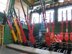
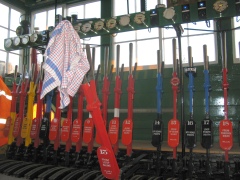
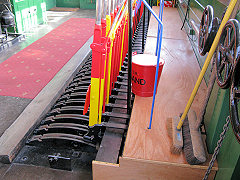
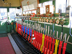
A side effect of this piecemeal conversion is the interesting ergonomic impact
of setting routes, with a combination of switches and levers. For example the photo of the lever
frame has the route cleared for the Up Golden Arrow through Platform 2. This involves alternating
from switch to lever several times i.e. 40 Outer Home (switch); 22 points & 37 Inner Home
(levers); 31 Platform Starter (switch); 5 points and 29 1st Advance (lever); 28 2nd Advance
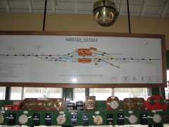
(switch). The Signalling diagram should help to explain the sequence.
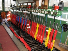
The remaining switches. |
The frame with many of the levers now in use. |
The Signalling diagram. |
Text and photographs: Chris Majer
Last Quarter 2011
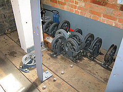
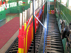
Work is progressing with the transfer of signals back to the lever frame. The stumps, pulleys
and wheels are in place from the box right up to the Up Second Advance Starter, a distance of about half a mile.
Two shunt signals at the north end of the station have just been added to the frame (13 and 18) allowing two of
the position light shunt signals to be removed. Approximately half of the levers are now in use with much of the
preparation work track-side ready for the next batch of conversions. The most tricky part of the process is the
stage-works required in the relay room to ensure the transfer of locking from electrical to electro-mechanical is
carried out safely.
The stumps in place northwards with the wires for 13
and 18 shunts. |
The lead-away at the signal box with the wires
ready for extending to the individual signals. |
Nº13 lever just after its function was
transferred to the frame. |
Text and photographs: Chris Majer
Second Quarter 2011
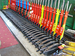
All points are now operated from the lever frame and the signals are being transferred. So far
numbers 39 (Up Calling-on) and 37 (Up Inner Home) have been transferred. The signal wire stumps and trackside
pulleys and selectors are being installed and the Down Yard Shunting Gong has been reinstated, operated from a
separate lever positioned by the South end windows. Some of the electrically operated semaphore signals are being
converted to mechanical operation to restore the traditional method of operation and to release signal machines
for the Kingscote resignalling project.
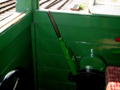
Levers in the Horsted frame. The black and blue one 'out'
of the frame is for points 17 and the lock and the red one for Signal 37. |
Newly installed Signal Wires leading away from the 'box. |
The lever for the Shunting Gong at the south end of the 'box
now reconnected to the Gong. |
Text and photographs: Chris
Majer
First Quarter 2010
The main change at Horsted Keynes is the ongoing transfer of
point operating functions from the switch panel to the lever frame. By the end
of March points 20, 22, 23 and 25 had been transferred. There have also been
changes to some interlocking controls to tighten up the requirements for the
signalling system. These include approach release of the Up Outer Home, where
reduced overlaps apply beyond the Up Inner Home, and changes to the Down Inner
Home when signalled into Platform 2 with an overlap set beyond the Down
Platform Starter towards the Ardingly Branch.
The main S&T activity is presently not for Horsted but is concentrating on
resignalling the north end of Kingscote Station with a new control panel
installed in the presently operational temporary Kingscote Signal Box, awaiting
the installation of track circuits, point machines and signal operating
equipment. This work is required for the operation of the Kingscote - East
Grinstead section.
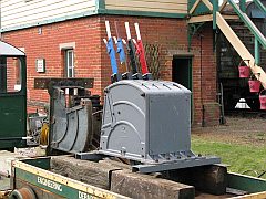
The other main activity is the preparation of equipment ready for installation
at East Grinstead. Two Ground Frames are required to work the run-round
facilities and the access to the Network Rail infrastructure.
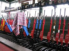
Levers in the Horsted frame.
The two black and blue ones 'out' of the frame are for points 20 and 25
and their locks. |
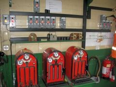
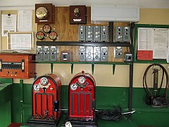
The panel instruments being installed at
Kingscote for the extension to East Grinstead. |
The two Ground Frames at
Horsted that will be installed for working the East Grinstead run-round
loop and access to Network Rail. |
Text and photographs: Chris
Majer
Third Quarter 2009
All of the locks and controllers are in place and are
progressively being wired up to the distribution wiring frame on the wall of
the locking room. When the links are inserted the wiring will be through
connected to the relay room on the other side of the Up Yard Ardingly
Siding.
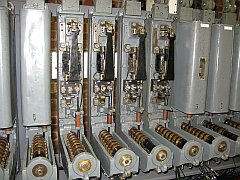
The photograph of the locks and controllers with the covers removed, reveals
the electric lever locks in the vertical plane and the controllers in the
horizontal plane. The locks are in addition to the mechanical locking and
provide, for example, back locks for the levers as well as point locking when
the track circuit shows occupied.
The commissioning of the lever frame will take place in phases with first phase
being the transfer of all points from the switches to levers in one session.
This will leave a period where the signalman will operate the points on the
lever frame but the signals by use of the temporary switches.
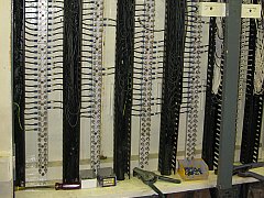
The distribution wiring
frame. |
Electric lever locks in the vertical plane
and controllers in the horizontal plane. |
Overview. |
Text and photographs: Chris
Majer
Second Quarter 2009
The Locks and Controllers have now been installed although
not mechanically connected yet to allow the Signalmen to operate the levers
with just mechanical locking so that they can operate the frame and get
familiar with the new arrangement.
The pullies for the signal wires have been installed and despite the
apparent random arranagement, have been carefully positioned so that the
wires do not interfere with each other and can be routed via the adjusters
for the long runs to the furthest signals.
| The latest items installed in the
locking room. |
Text and photographs: Chris
Majer
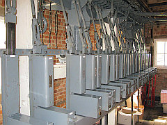
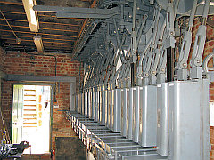
The mechanical locking is now complete and a walkway has
been constructed over the operating floor locking trays. The work has now
shifted to downstairs in the locking room where the electrical locking is
being applied.
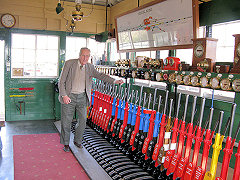
Bert Bassett, one of the
Bluebell's original Signalmen, inspecting the completed frame. |
The walkway that has been
constructed over the locking trays. |
Charles Hudson, S&T leader, in the
locking room downstairs where work has started on the electrical
locking. |
Text and photographs: Chris
Majer
First Quarter 2009
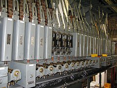
The new mechanical locking for Horsted Keynes lever frame
has been completed and provisionally tested. The mechanical actuators for the
Sykes treadles and the train waiting indicator have been connected up. Work is
currently progressing with fitment of pulley wheels for the wire operated
signals. Many of the mechanical signals currently electrically operated using
signal machines, will revert to mechanical operation and the recovered
equipment transferred to Kingscote in readiness for the East Grinstead
extension commissioning.
The lever frame inside the 'box
with the mechanical locking completed. |
The lever frame and block shelf
looking almost ready for use! |
The mechanical actuators for the Sykes
treadles and the train waiting indicator connected up under the Block Shelf. |
Text and photographs: Chris
Majer
First Half 2008
Most of the components to reassemble the locking are now
ready and the next stage will be to refit the interconnecting bars and dogs in
the locking trays upstairs (there are more downstairs) and attach the tappets
to the levers (see photo of the lever frame). The interconnecting bars and lock
dogs are ready and waiting downstairs under the signal box. Some components
will need to be customised as the assembly work progresses because of
tolerances with a large mechanism such as this. The picture on the right shows
two interconnecting locking bars that are so long that they almost go from one
end of the frame to the other!
The tappets sitting by the
frame. |
The locking pieces presently
underneath the 'box. |
The long interconnecting bars. (Click to see
the full image). |
Text and photographs: Chris
Majer