

|
|

|
|
Signalling & Telecoms: - Signals - Signal Boxes - Diagrams for East Grinstead - Kingscote - Horsted Keynes - Sheffield Park Bell Codes - Staff Instruments - Key-Token Instruments - Walkers Train Describers - Horsted Keynes Re-signalling 

Horsted Keynes Re-Signalling
|
||||||||||||||||||||||||||||||||
The frame for the new 'box diagram. |
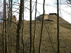
The Ardingly siding seen from the road. |
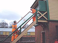
The new diagram being carried up the 'box steps. |
Text: Chris Majer and Adrian Lee, Photographs: Chris Majer (1 & 2) and Chris Dadson
Second Quarter 2006
On 8 April Chris Dadson paid another visit to the 'box and took these photos of the new diagram in situ, and of the continuing work on installation of the platforms 1 & 2 up starting signals.
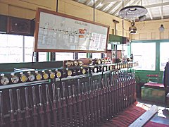
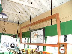
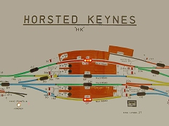
The new diagram fitted in place above the block shelf. More than 100 manhours went into the design and manufacture of the completed diagram. |
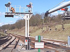
Work continues on the new platforms 1 & 2 up starting signals. |
With the installation of the new diagram at Horsted Keynes, the facility to operate Kingscote lighting remotely is now operational (part of the eventual switching out arrangements). When Kingscote is switched out, and when selected by the Kingscote control box, the signal lighting there repeats that at Horsted Keynes. Eventually the reverse will also be true.
Text and photographs: Chris Dadson
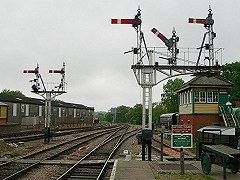
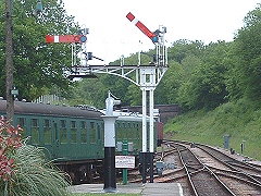
On Saturday 20 May 2006, at 4:30pm, the semaphore signals (activated by signal machines) at both ends of platform 2 were commissioned. The previously installed position light shunt signal on the south end gantry was removed giving a much improved presentation to drivers. The left hand signal (Nº8A) is the main signal reading to Sheffield Park and the centre short arm signal (Nº8B) reads towards the Ardingly Branch. The right hand arm applies to platform 1 but is not commissioned at present.
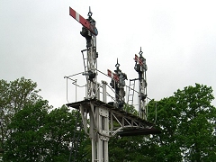
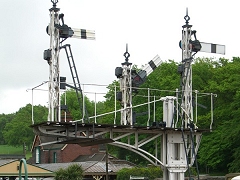
The new signals as viewed from the front and below. |
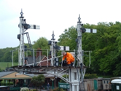
The reverse of the signals, with Nº8b "Off". |
A driver's view, once again Nº8b is "Off". |
Photographs: Chris Majer
Bill Dyer is here seen removing the redundant position light signal and route indicator. |
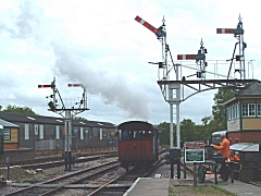
At 4:35pm the Engine and Brake Van of Footplate Days and Ways became the first movement to be signalled by the new Signal 8A, the Down Starting Signal for Nº2 Road. |
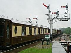
A little later, and with the weather a lot wetter, the Pullman Dining Train passes the signal on its journey back to Sheffield Park. |
Photographs: Adrian Lee |
Photograph: Chris Majer |
|
At the north end of platform 2, the main running signal, Nº31, applies to trains leaving for Kingscote via the Up Loop line whilst the previously used position light shunt signal has been removed. The left hand adjacent signal, Nº30, applies to platform 1 and is proved 'On', but does not have a signal machine at present.
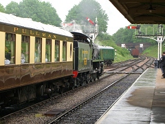
At the other end of the platform Signal 31, the Nº2 Road Up Starter, is seen at 7:35pm on the same day, cleared for the Golden Arrow on its way to Kingscote. |
The train passing the new signals, with U Class Nº1638 in charge. To the left of Nº31 is Nº30, the Nº1 Road Up Starter, which for the time being is fixed at Danger. |
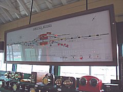
Part of the new 'box diagram, with the track circuit lights indicating that numbers one and four roads are occupied. |
Photograph: Adrian Lee |
Photographs: Chris Majer |
|
Most of the behind the scenes preparation work is now complete leaving the way clear to concentrate on the mechanical work required to commission the lever frame.
Text from Adrian Lee and Chris Majer.
Third Quarter 2006
A new Ardingly Branch Down Advance Starting signal post has
been erected and the fixed semaphore arm will be installed soon. The branch
track circuits have already been commissioned and it is the intention to be
able to run passenger carrying vehicles up to the new signal in due course.
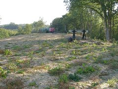
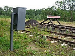
The branch siding has been extended over the new formation and new buffer stops
installed. The view back towards Horsted Keynes gives an idea of just how
extensive the reclaimed track bed is.
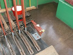
The design work for the relocking of the lever frame continues, the lever
strokes have been measured to ensure they are all identical, the tappets
measured for cutting the required notches and a new Annetts key mechanism has
been installed at the end of the lever frame. This will, in the future, be
operated by the long section token in connection with releasing the locking
when Horsted Keynes 'box is switched out.
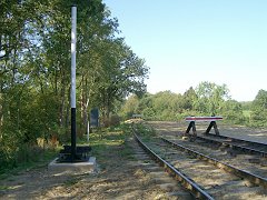
The new Ardingly Down Advanced Signal Post. |
The extended Ardingly Siding. |
The Annetts Key mechanism. |
Text and photographs: Chris Majer
Fourth Quarter 2006
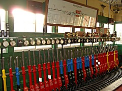
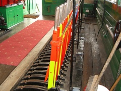
The levers have been painted and the lever plates giving the description of the lever function and locking added. The photographs indicate how impressive the frame now looks with the signalman making sure the levers still work even though it will be some time before the functions are transferred over from the switches!
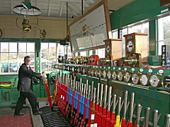
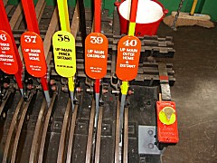
The Signalman testing a lever! |
Overview of the levers in the frame. |
Close-up view of some of the levers. |
Text and photographs: Chris Majer
Second Quarter 2007
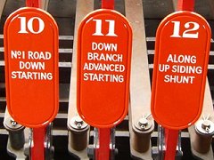
2007 has seemed to have begun on a quiet note as far as visible signs of work are concerned, which is not to say that the S&T department has been resting on its laurels, just that work has been more 'behind the scenes'. The Ardingly branch down advanced starting signal (Nº11) now has a fixed arm which allows trains to be signalled up to it. The branch has also been track circuited to just beyond this Nº11 signal, marked by a new location case and insulated block joints.
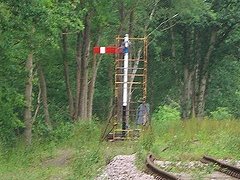
The branch advanced starting signal with arm attached and the new location case beyond. |
The lever for this signal in the frame. |
The new location case and insulated block joints just beyond the signal. . |
Text and photographs: Chris Majer
Third Quarter 2007
The work on the new mechanical locking has commenced with
the locking charts prepared and the locking trays removed for grinding down in
the carriage works, to allow the fitment of Stowell locks. The photograph shows
the finished trays being returned by Wickham Trolley.
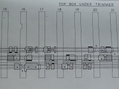
The Stowell locks introduced in the 1920s, are a clever mechanism to allow
conditional locking, of which there is a great deal at Horsted Keynes to allow
the required operational flexibility. The Stowell lock is characterised by the
diamond shaped lock dog in two parts that can slide horizontally and transfer
locking motion to adjacent channels in the tray. The extract of the locking
chart shows four in a row.
This work will continue for a considerable period of time being a highly
skilled and time consuming job. When complete there will be an extensive period
of testing before signalling functions can be transferred back to the lever
frame.
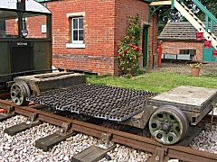
The finished trays on the Wickham Trolley. |
Extract from the locking chart. |
The lever frame with the mountings for the locking trays showing on the right. |
Some detail about the Stowell lock.
The diamond lock piece is made up of two precision machined parts that are
numbered and kept as pairs. They sit under and either side of the bar
separating the channels in the locking tray. This bar is fixed and acts as a
separating cover between the channels where a Stowell lock is fitted.
The photographs show the Stowell lock piece out of the locking tray,
illustrating how it is made and how it changes shape as the component parts
adjust to the forces experienced as the lever is pulled. Depending on the
conditions that apply when the lever is moved, the lock piece moves left/right
or top/bottom. The more conventional lock dogs in the adjacent channels will
then either move in sympathy (left or right) or be locked in position.
Text and photographs: Chris Majer

Return to BRPS Home Page, to the Timetable or to Special Events
Signalling & Telecoms: - Signals - Signal Boxes - Diagrams for East Grinstead - Kingscote - Horsted Keynes - Sheffield Park
Bell Codes - Staff Instruments - Key-Token Instruments - Walkers Train Describers - Horsted Keynes Re-signalling
Visitor Info. - Museum - Trust - Catering - Contacts - What's New - Projects - Locos - Carriages & Wagons - Signals - History - Other - Links - Search - FAQ
Why not become a BRPS Member? - Get more involved as a Volunteer
Page content last updated 11 September 2006 by Peter Richards. Last updated by Richard Salmon, 14 April 2022
© Copyright BRPS. Privacy Policy