Locomotives -
Operational Locos -
Locos under overhaul -
Locos on static display -
Locos formerly based on the Bluebell
Loco Roster -
Loco Stock List -
Loco Works News -
Join the Loco Dept
Atlantic Project - Background - Completion and launch - Next Projects: 'Normandy' and the Adams Radial Tank


Bluebell Railway Atlantic Group
2010 progress


1 February 2010
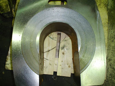
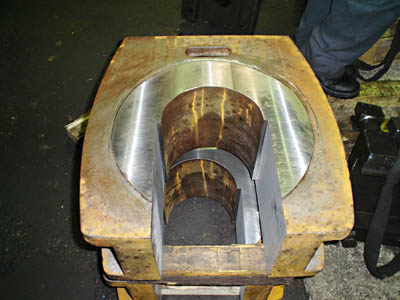
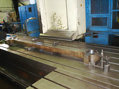
Thanks to Neil Hunt of Boro Foundry in Stourbridge we have these photos of progress on the rods and axle-boxes.
The first photo of an axle-box shows the "rough" concentric ring finish to provide a key for the white-metal surface that faces towards the back of the wheel. This was taken just before Christmas. The other photo of the axleboxes was taken on 26 January and shows the smoother inside face.
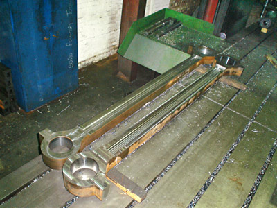
Below are two photos showing the roughing out of the coupling rods. They are being left for a while in this state to allow them to stabilise dimensionally before moving on to the next machining operation.
28 June 2010
Fred Bailey provides this update and photos, showing recent progress. There are also many other new components on order and eagerly awaited!
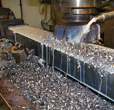
The first photo above shows the arm for the reverser being machined in Atlantic House. This arm transmits the movement of the nut (part of the screw assembly in the cab) to the lower reach rod.
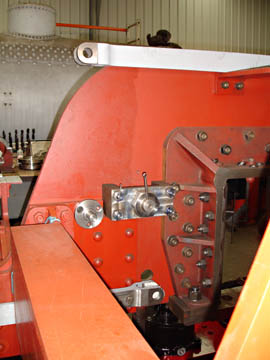
The second photo shows the upper and lower reach rods temporarily in position with the pivot for the lever (not yet made) in between. The round part is a pivot point for part of the drain cock linkage.
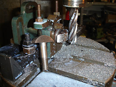
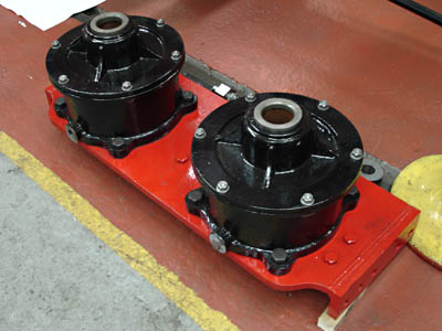
The next photo shows the finishing of the bolts for the air brake cylinders. As can be seen these have a narrow rounded head because there is insufficient room around the bolt hole for a normal bolt head. This detail is taken from the original drawings - not something we have dreamt up!
The two main 13" brake cylinders are now mounted on their cross stretcher. The special bolts are those around the top edge (in this view) of the cylinders.
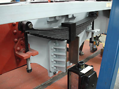
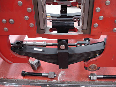
 The two photos above show the the leaf springs for the trailing axle (left) and the leading driving axle (right) recently arrived from our supplier. Note also that the grey undercoat is creeping forward.
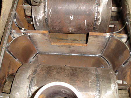
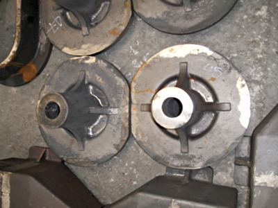
Take a good look at the photo on the right - this is the last time this will be seen! You are looking inside the steam chest assembly. At the top with an 'A' on it and the bottom with an 'F' are the steam chests proper, where the steam arrives having come from the boiler through the regulator. After passing the piston valve and pushing the piston in the cylinder it comes out past the same valve on route to the blastpipe and chimney. The area between the rounded valve chests is where the exhaust steam arrives. The quarter round tubes help 'streamline' the passage-way and the divider plate crossing left to right prevents the exhaust from one cylinder trying to go into the port for the opposite cylinder. The lid is now welded over all of this. We painted arrows inside to tell the steam which way to go!
October 2010
This report, illustrated by Fred Bailey's photos, shows recent progress with many new components having been completed in the workshop, or delivered from external contractors.
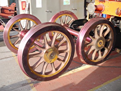
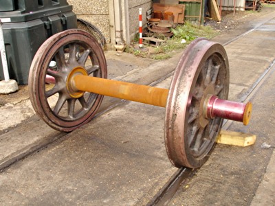
Fresh from I. Riley's we now have the brand new wheels, axles and tyres ready for fitting to the bogie, and the wheelset for the trailing axle.
The trailing wheels are actually from an S15 tender, which are of the correct size, number of spokes etc. and are fitted onto a new axle.
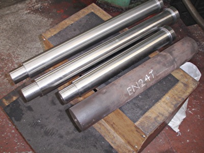
Below are the bogie swing link pins - the longer ones are 25" long and are within 3 thousands of an inch of parallel along the whole length, without making any adjustments to the lathe tailstock. This is more than adequate to do the job required.
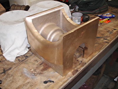
The bronze item is the oil tray for the driving axlebox. The ones for the coupled wheels are well advanced, and these will be finished to fit the axleboxes once they are received.
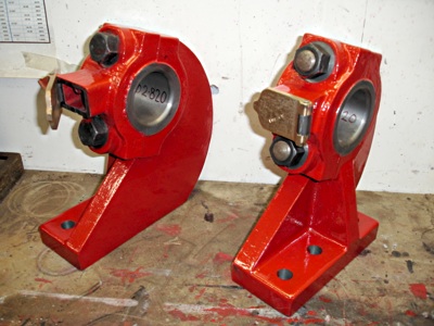
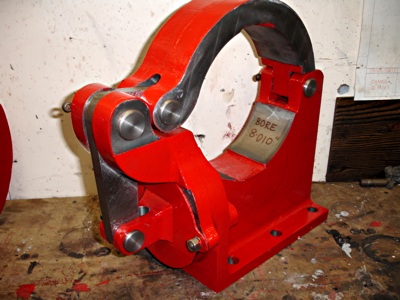
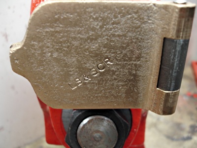
These next items are the bearings for the weigh shaft (right), together with the weigh shaft clutch below. Note the genuine "Brighton" oil box lids!
The weigh shaft is attached via the reach rods to the reverser in the cab, and via the lifting links to the expansion link of the Stephenson's valve gear.
The clutch is used to steady the shaft and to stop the reach rods and the reversing screw from taking any of the stresses produced by the movement of the valve gear components when the engine is in motion.
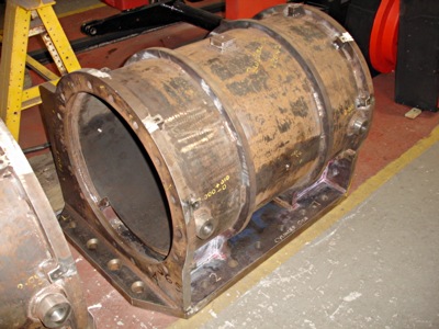

On the left is a photo of one of the finished cylinders, now awaiting heat treatment.
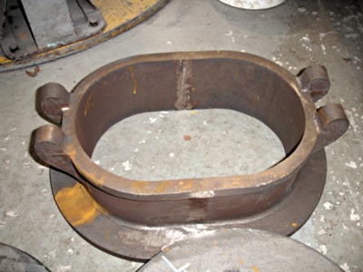
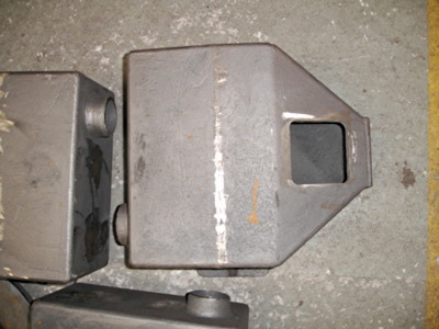
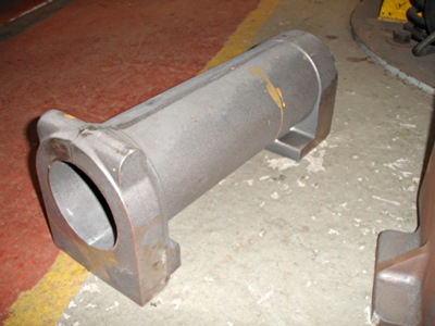
The remaining photos below are of the latest castings received on 16th October from Cerdic Foundry.
The first two show the tender water filler casting and a sandbox casting.
... and finally the reverser body, and the front and rear valve chest covers.
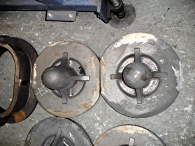


More recent news updates
- 2011 - Coupling rods and axleboxes delivered, reverser mechanism completed, crossheads cast.
- 2012 - Valve and cylinder liners fitted - lifting and reversing arms and axlebox crowns delivered - castings for mudhole doors, regulator and whistle valves, reversing shaft clutch, blast-pipe cap, crosshead slippers, 'J' pipe and eight eccentric halves received - Bogie and trailing axle now support the frames - Valve chest and cylinders fitted to frames, covers fitted, and pressure tested.
- 2013 - Cylinders, valves, slidebars and crossheads completed - driving wheels completed - valve gear components delivered - lifting frames constructed.
- 2014 - Weigh (reversing) shaft and air-clutch fitted, axleboxes metalled, machined and fitted, wheel rotators constructed, eccentric rods, valve and reversing gear, pipework for brakes and steam heat completed, locomotive wheeled, cylinders clad and crossheads fitted.
- 2015 - Rolling Chassis completed with all motion erected. Running plates and splashers completed, along with cab sides and front.
- 2016 - Connecting and coupling rods fitted, valves set. Superheater header delivered. Revision of boiler internal pipework completed. Cab roof riveted together and fitted. Mud-hole patches welded into boiler. Flue tubes (with screw ends welded on) delivered.
- 2017 - Major progress on the boiler overhaul, and with the safety valves.
- 2018 - Boiler tubes fitted, tender made mobile, complex parts of the boiler cladding made.
- Most recent news.
Older news updates
- Background and early progress
- September 2001: Repairs to tender chassis.
- More photos of the project (1999-2002).
- March 2002: Modification of front end of tender.
- November 2004: Loco Frames ordered.
- December 2004: Bogie frame components arrive - also Feb.2005 news report.
- 2005 - Loco main frames arrive - tender frames nearly completed - start of construction of the shed.
- 2006 - Loco driving wheel castings delivered - drilling of the main frames and hornguides - building of the shed completed.
- 2007 - Main locomotive frames erected.
- 2008 - Components for the cylinders and valve chest delivered - frames riveted - forged billets for connecting and coupling rods delivered.
- 2009 - First motion parts water-jet cut from forged blanks - bogie frames assembled.
Project Funding
A fund raising appeal for the cash required to complete the project was launched in 2000, and a combination of gifts made via the Bluebell Railway Trust, and standing orders set up to provide a steady income to the project have now made over a third of the total available. Whilst this has provided funding for the present work, more is going to be needed to complete the project, and the best way in which you can help is by setting up a small, regular, standing order to the Bluebell Railway Trust under Gift Aid, since this enables the Trust to reclaim the basic rate tax you have paid, and (if you are a higher rate tax-payer) enables you to reclaim some tax as well.


Return to BRPS Home Page,
to the Timetable or to Special
Events
Atlantic Project - Background - Completion and launch - Next Projects: 'Normandy' and the Adams Radial Tank
Visitor Info. -
Museum -
Trust -
Catering -
Contacts -
What's New -
Projects -
Locos -
Carriages & Wagons -
Signals -
History -
Other -
Links -
Search -
FAQ
Why not become a BRPS Member? -
Get more involved as a Volunteer
Your ideal Film/TV location?
 Photos and reports from Fred Bailey.
Page maintained by Richard Salmon
© Copyright BRPS. Privacy Policy
|
