Locomotives -
Operational Locos -
Locos under overhaul -
Locos on static display -
Locos formerly based on the Bluebell
Loco Roster -
Loco Stock List -
Loco Works News -
Join the Loco Dept
Atlantic Project - Background - Completion and launch - Next Projects: 'Normandy' and the Adams Radial Tank


Bluebell Railway Atlantic Group
2014 progress


March 2014
Just in case you were wondering just what we have been doing the last couple of months, here are some bits and pieces (with thanks to Fred Bailey). As always, click on the photos to see enlargements.
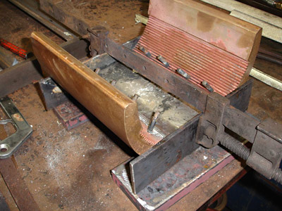
The first photo, above, shows an axlebox crown in the process of being white-metalled. The pins are to stop the molten metal filling up the oil feed holes.
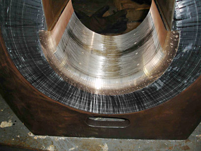
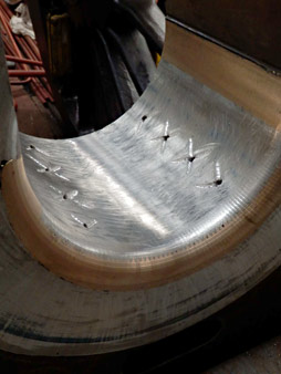
The next shows a finish machined crown fitted in the axlebox, which is upside down. The finish shows a light scraping to "rough up" the machined finish to provide small cavities to retain oil. The 8 white spots in the white metal are small wooden plugs to prevent swarf from blocking the oil feed holes.
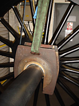
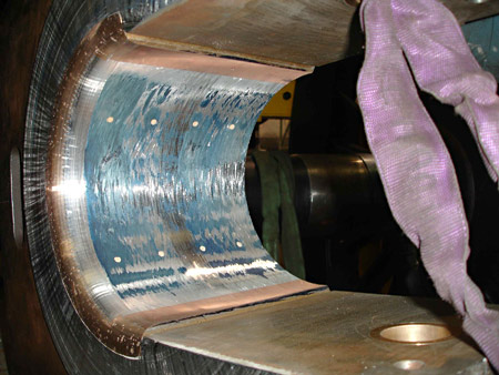
 Above, the axlebox is shown resting on the axle, which has had a thin coating of Engineer's Hi-spot blue applied to it. The box is then partially rotated and pushed too and fro' to transfer the markings to the white-metalled surface of the crown.
In the next photo, the bearing shows the blue markings, with a good proportion of blue (i.e. no high-spots), but with deliberate low-spots for oil retention.
The next step is shown on the left, where the finished crown (again upside down) has small cross cuts added to help lead the oil out onto the bearing.
Whilst there is nothing in this process which is different from that routinely done whenever a bearing needs re-metalling, we none-the-less thought it interesting to show the process in detail.
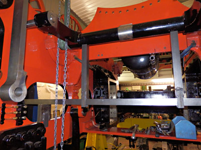
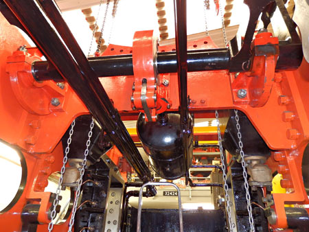 The next photo above shows the weigh or reversing shaft (the black shaft spanning the frames towards the top of the picture) being supported on some accurately machined support blocks so as to achieve the original drawing dimension given from the centre line of the axles to the centre of the weigh shaft.
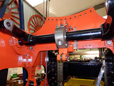
The weigh shaft trunnion bearings are shown in the second photo above, in their final position secured by fitted bolts. The drum in the centre of the shaft is part of the weigh shaft air-operated clutch, which is used to steady the shaft and to stop the reach rods and the reversing screw from taking any of the stresses produced by the movement of the valve gear components when the engine is in motion. The housing is temporarily bolted in its correct position while the fixing holes are drilled through and then reamed for more fitted bolts. Note that we had to remove the paint from the stretcher to get the housing to clear the drum (by a few thousandths of an inch).
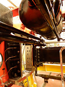
On the right we see the whole assembly in position looking towards the rear of the engine. All this had to be fitted before the pipework went in. There are three pipes immediately over-head in this view, all three being for the air brakes, as is the reservoir situated behind the clutch. The large pipe to the left of the tank is the vacuum train pipe and the one above it is for the steam for carriage warming. The Brighton Atlantics only had clean lines because everything is hidden away between the frames.
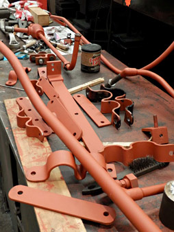
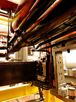 Next above are just some of the pipes, pipe clips and brackets that have been made to support the various pipes.
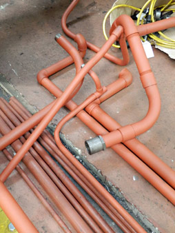
Pipes for air, vacuum and steam heating that have been fitted, then removed for access to other parts and for painting are seen next.
Third we see the air reservoir and the vacuum and steam heat pipes. Note that the pipes veer to the left then drop down under the boiler support stretcher. The reasons for this are a) to allow some room to the front of the throatplate of the boiler, providing access to the two mudholes located in the area for washing out of the boiler, and b) to get the pipes to run alongside the ashpan so as not to hinder access to the damper door through which ash is raked into the pit.
On the right we see the air pipes, again located as they are for the same reasons as above.
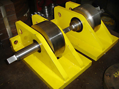
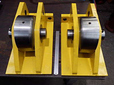
 In order to rotate the driving wheels to allow us to find, quantify and rectify the errors (probably small) in the crankpin / eccentric keyways left to us by one of the three sub contractors, we are just finishing the manufacture of some rotators. They will also be used when the time comes for valve setting.
First above are the "driven" pair of rotators, then the idler pair. Further photos of the complete units in use will follow.
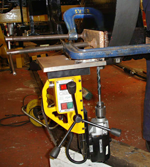
Finally (left): when we find that we have forgotten something that needs doing before wheeling (and you can't turn the chassis over to get at something) then a magnetic based drill is a must! In this case, it's brackets to hold the sand-pipes which needed to be fitted.
April 2014
A few more photos of recent progress from Fred Bailey, to keep everyone informed, whilst supporters and subscribers to the project will soon get more in the next printed newsletter
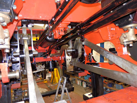
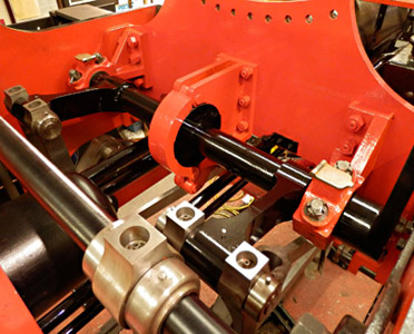
This and the following pictures show the valve gear now erected between the frames. In this view the two rods forming a 'V' on the right are the eccentric rods. They are attached to the top and bottom of the expansion link. The brassy coloured item above these is the sand trap at the base of the sandbox.
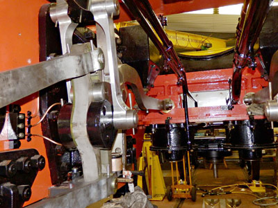
Below is a closer view of the expansion link on the left side of the engine looking forward. One can also see the rod that is formed to rise up and over the leading coupled axle. The taper pins here have not yet been cut to length or their tails opened out.
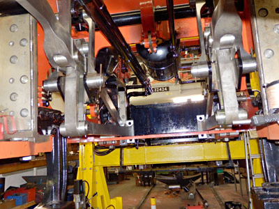
Also below is another view of the valve gear, this time looking towards the rear.
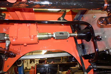
 These are the adjusters between the valve rods and the intermediate guided valve rods. The threads on each rod are both right handed but of different pitches, so if the hexagon portion is turned, the valve rod moves by the difference in the pitches of the threads so giving a fine adjustment. Either side are lock nuts with teeth around the periphery. Not seen in this view are the toothed locking tabs provided to lock the lock nuts. (All similar to GWR practice). The rectangular hole is for slip gauges. These can be inserted between the ends of the rods so that when being re-fitted the valve position can be reproduced to that set originally. The distance figure once known will be stamped on the hexagonal adjuster.
The first photo below shows the weigh or reversing shaft together with (in the centre) the air clutch. The four rods descending from the two horizontal arms are the lifting links, attached to the expansion links. In the immediate fore-ground (out of focus) is the top of one of the suspension levers. These support the intermediate valve rod which swings on these levers.
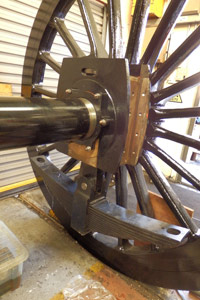
Next is the right leading driving wheel complete with axlebox and leaf spring in position.
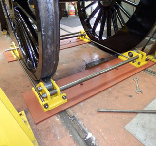
The third shows the wheel rotators in use. By simply tightening the nuts on the four longitudinal stay rods the rotators on their baseplates are pulled together, and so the two wheels on their axle, weighing 4 tons, are lifted slightly clear of the rails. On the further rotator there is a shaft with a square end on it. This is linked to an identical unit opposite. A square drive ratchet brace can then be used to turn the wheels. Extra effort is required when both balance weights in the wheels are starting to rise and "braking" required when they are decending. These will next be used when the time comes for setting the valves.
Atlantic House will be open for sales, and for our supporters and subscribers, on 21 and 22 June. We are also open for sales on the Bluebell's Model Railway Weekend, 28 and 29 June.
May 2014
We have another great set of photos, showing recent progress, with thanks to Fred Bailey. Your support is vital to the success of the project, and donations and sponsorship of components are important ongoing methods of support - could you sponsor a patch screw for the firebox or a cylinder stud, or maybe one of the larger components, on the updated list?
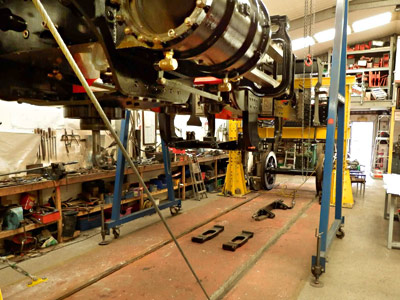
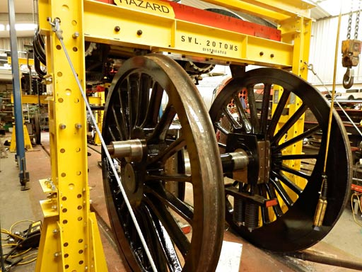
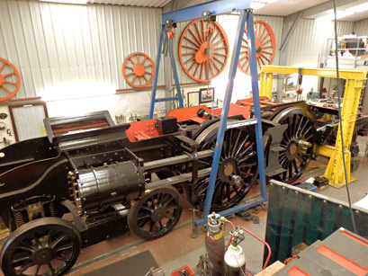
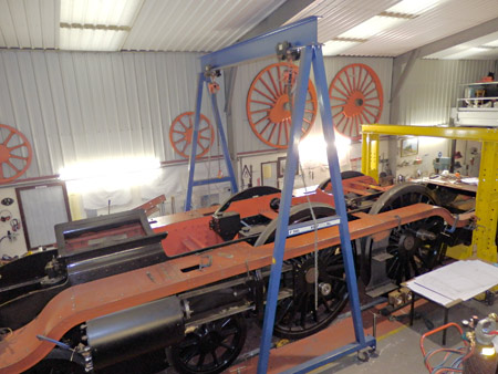
The photo on the right shows the chassis jacked up, using the lifting frames to the maximum height, which is required to clear the driving wheels so that they can pass under the front buffer beam.
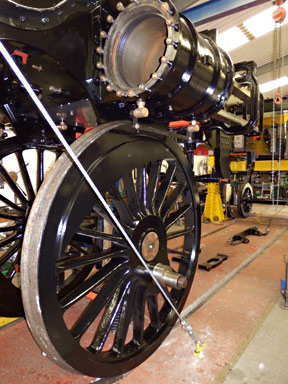
The next two photos below show the main driving wheels passing under the lifting frame and the front buffer beam, and under the cylinders - the height of the wheel from floor to the top of the wheel flange is about 6'9".
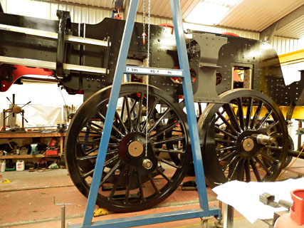

On the left we see the chassis ready for lowering onto the driving wheels.
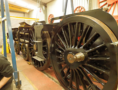
The next two photos, below, show the chassis resting about 10" above the final running height, in order for a few more jobs to be finished off between the frames. Once fully lowered access for such jobs will become even more restricted. A pit would have improved this situation but we are safer working without one - there are less pitfalls!
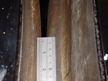
In the next photo you can start to appreciate just how close together the driving wheels are, something which causes modellers at smaller scales some issues due to non-scale wheel flanges! As designed, the gap between the driving wheel flanges is about 5/16" (8mm).
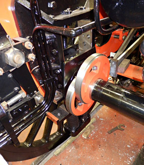
Subsequent progress has included mounting the first pair of eccentrics on the driving axle, as seen in the final photo below.
Work is also proceeding at present on the fitting of the slippers to the crossheads, using shear-headed phosphor bronze screws, prior to them being white-metalled and machined to fit the slide-bars. The Westinghouse pump has been refurbished and is being re-assembled ready for (temporary) installation. This is primarily to enable the working out of the final routing of the pipework. Machining work at present is concentrating on making the bolts that hold the eccentric rods to the eccentric straps. These are to be followed by the more complicated ones that hold the pairs of eccentric straps together.
Don't forget that Atlantic House will be open for sales, and for our supporters and subscribers to get a closer look at progress, on 21 and 22 June. We are also open for sales on the Bluebell's Model Railway Weekend, 28 and 29 June.
August 2014
Our four open days, plus other work taking priority for Tony and the summer in general, has slowed work down a little of late, but great progress has still been made, as seen in this report and photos from Fred Bailey.
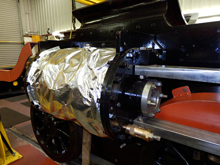
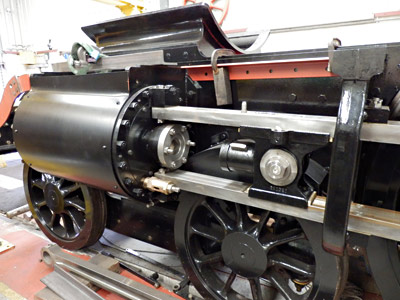
The photo on the right shows the lagging material wrapped around the cylinder. We are not using fibre glass these days as it tends to trap moisture and encourage corrosion.
The first photo below shows the lagging sheet on the cylinder plus the crosshead sitting between the slidebars. Also in this view is the splasher over the bogie wheel to stop most of the dust off of the rails settling on the slidebars to make a nasty grinding paste.
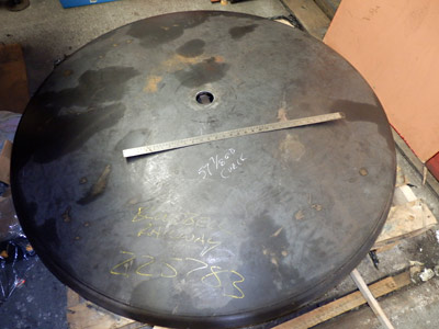
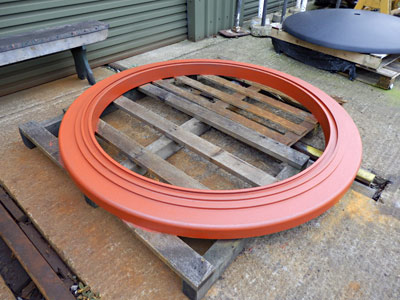
We recently received our smokebox outer door, which is pressed and spun from 3/8" steel plate.
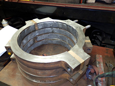
The next photo, below, shows the eccentric straps, now all lined with white metal and ready for the final machining. The special bolts for these are well underway and will be finished shortly.
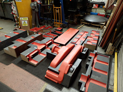
The final photo shows a whole pile of work. Thanks to Roy and Syd our pattern makers this lot should, with luck, produce the main superheater header casting. Quite a nightmare to get one's head around, having to think backwards and also about where the split lines in the mould will be plus making loose pieces for parts that would otherwise not be able to be removed from the sand when getting the pattern out to leave the space to be filled by molten metal. Roy has also recently produced the patterns for the oil-boxes.
We are on the verge of ordering the smokebox front and the four cast footsteps that are to be found on the top of the running plate either side of the smokebox, and either side of the firebox (on the curved portions). So look on our sponsored items list if you wish to sponsor one of these - only three left now, I think.
Work is proceeding on the footplate valences and running plates at present. Once these are done then we will turn to the splashers for the driving and coupled wheels. Pre-formed angle irons and laser cut plates are already in stock for these items. We are also now in the process of cleaning up the water-cut profiles of the coupling and connecting rods and are machining the bearings and wedges etc. for these.
December 2014
Thanks as ever to Fred Bailey for this report and accompanying photos, showing recent progress on the project.
On the right is an overall view of the chassis with the running plates taking shape, so producing the clean looks that characterised the Brighton H2s. The amount of work in these is quite staggering and it is difficult stuff to deal with being heavier than it looks (all 3/8" plate and 5" x 3" x 1/2" angle etc.), and mostly out of reach of our swing arm crane. We are tending to work in much the same manner as on the original locomotive using a lot of rivets and specially made countersunk bolts. The splashers are also in production although not shown here. Again these are all riveted. Welding is possibly quicker but distortion would be very difficult to control, not of course having been a consideration in the original design. As an example, each of the smaller leading splashers have a total of 88 of the 5/16" rivets and 23 of the 3/8" rivets!
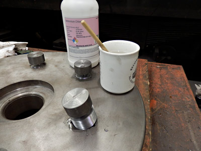
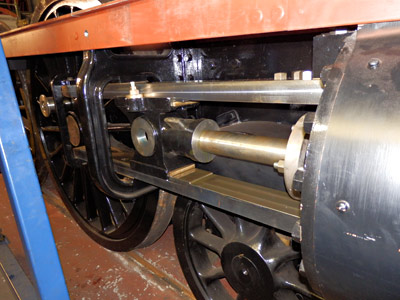
We have changed our piston design to be more like later practice as used on the BR Standard locomotives. These have simple disc type pistons which have six hollow segments in them to cut down on the reciprocating masses. These cavities have holes to both sides in order to allow the removal of the sand from the casting process. To leave such holes would not be conducive to the success of operation, so they are closed using something akin to a steel boiler stay - a continuous thread reduced in the centre. As seen in the first photo below, these are screwed into tapped holes in the piston. In order to help make them steam tight we have painted the threads with a strong solution of sal-ammoniac (as called for on the BR drawings).
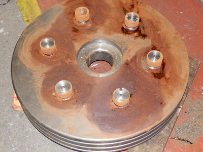
The result is something that we normally try to avoid at all costs - a lot of rust. This picture was taken three days after the previous one. The head is then cut off and the end of the stay punched into three recesses filed in the thread in the piston. Just for good measure the edge of the thread is then riveted over all around its edge. Hopefully they will not come loose!
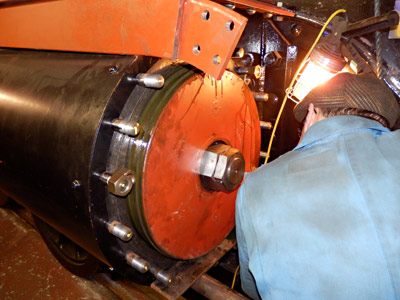
After fitting the heads to their rods then the pistons are fitted with their rings and the installed into the cylinder. Note the fixing nuts in the photo below; again BR practice. One large nut threaded right handed followed by a smaller left-handed nut with a different pitch thread with a tab washer to lock the two together. On railways, retention of all parts is crucial.
After all the above the piston rod is coupled up to the crosshead. In this photo from 23 November, the taper key (passing through the crosshead and the tapered end of the piston rod) has yet to be fitted with its locking key.
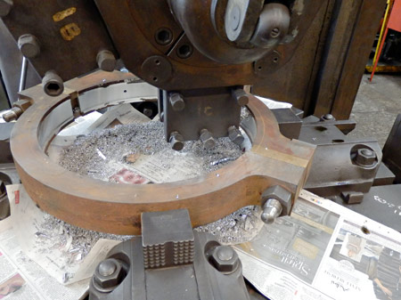
 The photo on the left shows a complete eccentric strap set up on the vertical lathe, having the white-metal liner machined ready to fit on to the eccentrics themselves. These items will be painted prior to fitting.
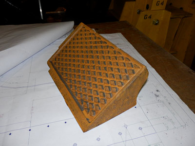
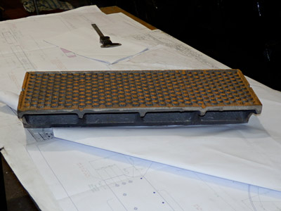
More items related to the running plates are seen in the photos below. First we see one of the steps that go on top of the rear curved section of running plate, next to the main driving-wheel splasher.
The next shows the larger step on the running plate at the front alongside the smokebox. All four of these castings (of the two designs) were produced from polystyrene sacrificial patterns produced directly from our 3D CAD drawings.
Also produced by the same method was the smokebox front ring, cast complete with the recessed groove to take the smokebox door seal. Normally the smokebox front ring and the seal holder are separate parts riveted together, but due to problems in obtaining a steel channel section pressed to shape and then rolled for the front of the smokebox and the extra work involved in riveting a fairly weak steel casting to it, the above method was used. As we have not the facilities to turn this diameter of component it came in fully machined.
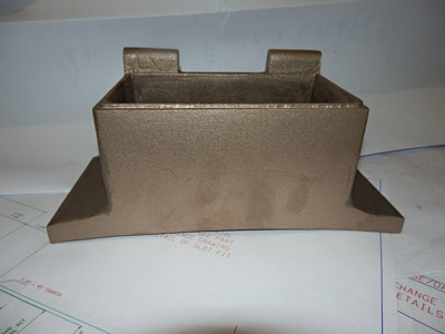
Finally, one of the cast oil boxes that fit on top of the main wheel splashers and are used to fed oil to the axleboxes. This time the patterns and core boxes were made by our in house volunteer pattern-maker.


More recent news updates
- 2015 - Rolling Chassis completed with all motion erected. Running plates and splashers completed, along with cab sides and front.
- 2016 - Connecting and coupling rods fitted, valves set. Superheater header delivered. Revision of boiler internal pipework completed. Cab roof riveted together and fitted. Mud-hole patches welded into boiler. Flue tubes (with screw ends welded on) delivered.
- 2017 - Major progress on the boiler overhaul, and with the safety valves.
- 2018 - Boiler tubes fitted, tender made mobile, complex parts of the boiler cladding made.
- Most recent news.
Older news updates
- Background and early progress
- September 2001: Repairs to tender chassis.
- More photos of the project (1999-2002).
- March 2002: Modification of front end of tender.
- November 2004: Loco Frames ordered.
- December 2004: Bogie frame components arrive - also Feb.2005 news report.
- 2005 - Loco main frames arrive - tender frames nearly completed - start of construction of the shed.
- 2006 - Loco driving wheel castings delivered - drilling of the main frames and hornguides - building of the shed completed.
- 2007 - Main locomotive frames erected.
- 2008 - Components for the cylinders and valve chest delivered - frames riveted - forged billets for connecting and coupling rods delivered.
- 2009 - First motion parts water-jet cut from forged blanks - bogie frames assembled.
- 2010 - Cylinders and valve chests fabricated, air brake cylinders completed, bogie and trailing wheelsets completed.
- 2011 - Coupling rods and axleboxes delivered, reverser mechanism completed, crossheads cast.
- 2012 - Valve and cylinder liners fitted - lifting and reversing arms and axlebox crowns delivered - castings for mudhole doors, regulator and whistle valves, reversing shaft clutch, blast-pipe cap, crosshead slippers, 'J' pipe and eight eccentric halves received - Bogie and trailing axle now support the frames - Valve chest and cylinders fitted to frames, covers fitted, and pressure tested.
- 2013 - Cylinders, valves, slidebars and crossheads completed - driving wheels completed - valve gear components delivered - lifting frames constructed.
Project Funding
A fund raising appeal for the cash required to complete the project was launched in 2000, and a combination of gifts made via the Bluebell Railway Trust, and standing orders set up to provide a steady income to the project have now made over a third of the total available. Whilst this has provided funding for the present work, more is going to be needed to complete the project, and the best way in which you can help is by setting up a small, regular, standing order to the Bluebell Railway Trust under Gift Aid, since this enables the Trust to reclaim the basic rate tax you have paid, and (if you are a higher rate tax-payer) enables you to reclaim some tax as well.


Return to BRPS Home Page,
to the Timetable or to Special
Events
Atlantic Project - Background - Completion and launch - Next Projects: 'Normandy' and the Adams Radial Tank
Visitor Info. -
Museum -
Trust -
Catering -
Contacts -
What's New -
Projects -
Locos -
Carriages & Wagons -
Signals -
History -
Other -
Links -
Search -
FAQ
Why not become a BRPS Member? -
Get more involved as a Volunteer
Your ideal Film/TV location?
 Photos and reports from Fred Bailey.
Page maintained by Richard Salmon
© Copyright BRPS. Privacy Policy
|
