Locomotives -
Operational Locos -
Locos under overhaul -
Locos on static display -
Locos formerly based on the Bluebell
Loco Roster -
Loco Stock List -
Loco Works News -
Join the Loco Dept
Atlantic Project - Background - Completion and launch - Next Projects: 'Normandy' and the Adams Radial Tank


Bluebell Railway Atlantic Group
2017 progress


May 2017
Fred Bailey supplied this update in early May, so apologies for the time taken to get it online.
 It has been some time since we have provided an update on the Atlantic, because the progress that is being made is generally not very showy, but does provide the basis for the next major stages. Obviously the boiler is our priority but various small items have added up to a further delay.
The replacement plates with new openings for mud hole doors are now fully welded into position, the welds have passed their stringent examination satisfactorily and new copper stays to replace those removed with the old plate are now in position and await final heading.
We are now ready to start riveting the foundation ring, but due to our team's more senior age profiles we are awaiting a time when one or two of the younger, fitter, skilled boiler team members from the main works can assist us. Unfortunately they are very busy working on boilers that are needed to provide the motive power to service the core business of the railway. We hope to get underway in June with this work.
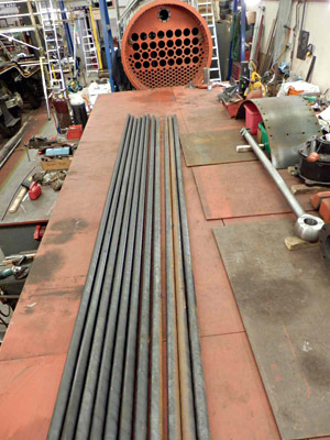
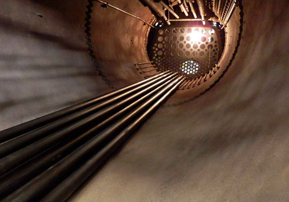
The first photo shows a sight not seen for a long time. We have cleared all of our material stocks off of the top of the tender chassis and put the larger components on one side to allow us to start preparations for tubing the boiler. We intend using a special coating on these tubes to give them a good start in life within our boiler. There is quite a lot of work here as all 134 small tubes and 32 large tubes, all 16 feet long, need to be thoroughly de-greased and then given two coats of the preservative "paint". The first few tubes can be seen laying on the tender floor. We were initially intending to raise the boiler to tube it, but we have found that this will not now be necessary.
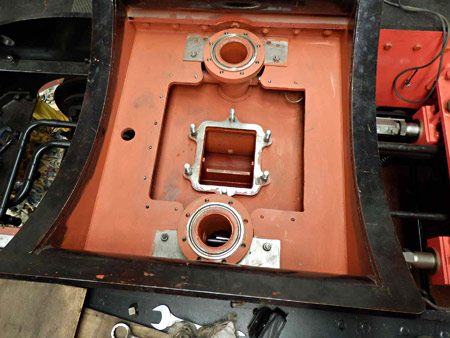
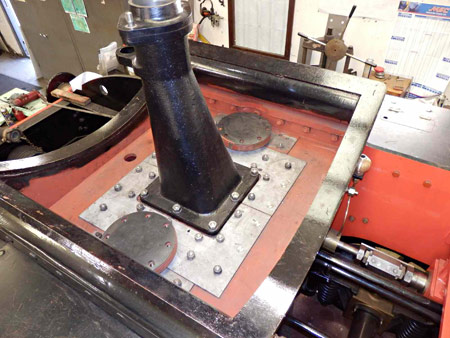
The photos below are an earlier view of the two steam pipes in the base of the smoke box saddle (round flanges) leading into the valve chests and in the centre the exhaust exit flange, and a later view showing the blanking plates to help protect the top of the valve chests from ash etc. and the upper blast-pipe now in position - although it will be removed when adding the boiler and smoke box to the chassis.

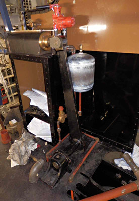

At the rear of the engine (as seen on the left) more pipes are getting installed along with another air reservoir that provides the air to power the reverser.
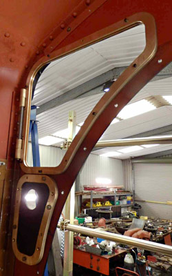
Also in the cab (right) we have been fitting the spectacle plate window frames and (not shown) the catches that keep them closed.
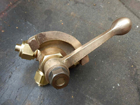
Below is the valve, mounted on the cab side above the reverser, that operates both the clutch to lock the weigh shaft and applies air to the reverser to assist in reversing the engine. No air assist is required to put the engine in forward gear.
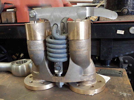
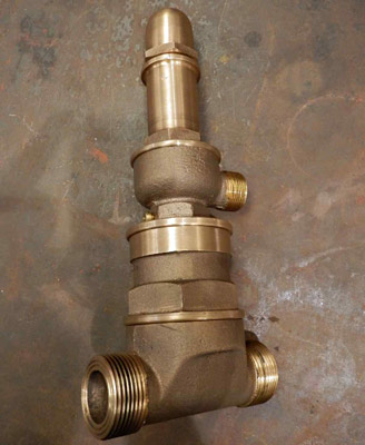
The double Ramsbottom safety valves, below, are now virtually complete. These will be pressure tested shortly to prove the body integrity and then will be re-assembled and approximately set for the blowing off pressure. Once that is done, washers are made to go between the counter-bore in the body and the underside of the adjuster to ensure that no further adjustments can be made that would increase the set pressure.
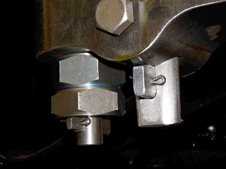
For some time the chassis has looked complete, and in essence it was, however it is not complete until all the fixings are tightened and retained. This operation is best left to be done as one operation moving methodically from part to part. Steam locomotives try from the first moment they move to reduce themselves to their component parts by whatever means possible and this is where the very smallest of components become the most important.
It is difficult to show the amount of work involved in doing this work but this next picture below shows an easily accessible example outside the frames. This is the big end cotter and taper bolt with its nuts behind it. Note the cotter has pinch bolts in the side, plus a cotter fitted tight to the underside of the rod, which in turn is split pinned. The taper bolt has a nut and locknut again with a fitted cotter and split pin. This sort of thing can be found throughout the chassis especially between the frames where it can't be easily seen.
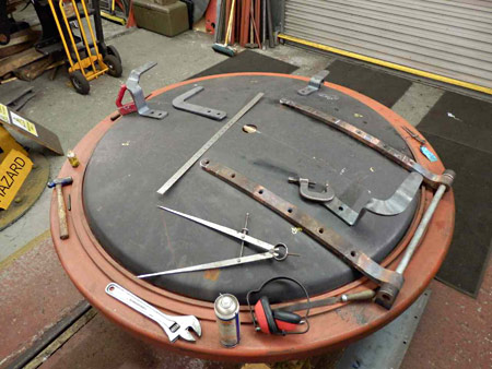
Work has started on fitting up the smokebox door and its surround. The hinges were rescued off of the smokebox that came attached to the boiler all those years ago. With some slight modifications they seem to fit very well to our new smokebox door. The hinges would be difficult and expensive to manufacture today, being forgings with twists and bends to make them fit the door.
October 2017
Fred Bailey supplies another update, with photos showing recent progress on this project.
The component sponsorship list has also been updated.
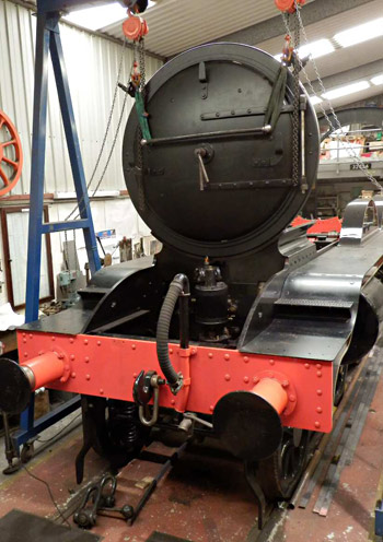 On the right we have a view of the chassis with the smokebox door and its surround sitting on the smokebox saddle. Its true position is about a foot nearer the front of the engine, so that the Westinghouse pump will actually be under the smokebox. Hardly ideal for maintenance purposes but to fit it to the smokebox side would severely limit forward visibility and might also foul the loading gauge, and space between the frames is (and was) taken up with loads of other equipment. Hence the position selected by the LB&SCR for the pumps on the H classes of Atlantic.
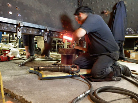
As stated earlier the boiler has been our priority and the first row of rivets around the foundation ring have been removed and are now re-riveted by our two boiler smiths from the main workshop assisted by a couple of us from the Atlantic crew. Work on boilers is a job that is not only hard physically, but demands a great deal of thought, planning and (although not realised by the majority) precision. The folks that do this work day in and day out are the only reason you can see preserved steam ANYWHERE today! So be thankful there are such people prepared to do this work and we ought to go out of our way to ensure we keep their services.
The photograph below, although a little blurred (there is not time to pose for cameras), shows a rivet about to be put in its hole prior to being double gunned down. This means two hand held rivet guns being used, one on each end of the rivet. The remaining rivets in the upper row have now been removed although a good few were in no mood to come out without a fight, but never the less we are now ready to finish the foundation ring riveting once we can obtain the assistance of our (younger and fitter) boiler smiths once they can find a gap in their more important work in the main loco workshops which obviously must take priority.
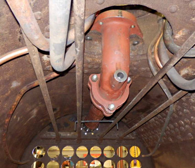
The second photo below shows the 'J' pipe, on top of which sits the regulator, and the main steam pipe going out through the front tube-plate. We have conducted a pressure test on the joint between the 'J' pipe and the steam pipe and it seems to be satisfactory, so the studs to take the superheater header have now been installed, so filling up the holes that can be seen around the steam-pipe.
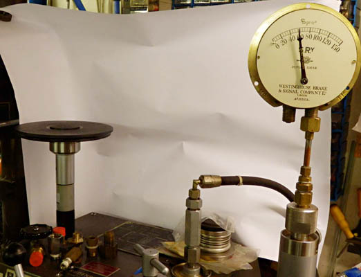

On the left is a picture of the start of the check calibration on one of the movements within the Westinghouse Duplex pressure gauge. This is being carried out on a dead-weight pressure gauge tester that works via a "sack" containing water that is pressurised by the oil used in the tester itself. This then ensures that the oil in the test machine does not come into contact with the gauge internals. The outer needle is not fitted whilst checking the inner one as shown.
A little while ago we produced some 3D CAD models of the various cast parts that go towards the making of a Westinghouse air pump governor. The patterns and castings were then made and machined. These together with all of the many other parts have now been produced by others with the result we now have in stock a brand new Westinghouse pump governor, seen in the first photo below. The machining and assembly, not to mention the "tinkering" required, have produced an excellent item that we are told works like a dream as it has been tested in service on an engine.
At long last we have now made a start with the painting and installing of the boiler tubes, as seen below. Each tube gets two coats of Apexior prior to installing it into the boiler. This is quite a slow job - the painting and drying of the tubes a few at a time taking a lot longer than their fitting. The superheater flues will be slower still as there are handling problems due to their weight to be considered. Putting them in their holes is the easy part as they all then have to be expanded and beaded. "Fun" to come!


More recent news updates
- 2018 - Boiler tubes fitted, tender made mobile, complex parts of the boiler cladding made.
- Most recent news.
Older news updates
- Background and early progress
- September 2001: Repairs to tender chassis.
- More photos of the project (1999-2002).
- March 2002: Modification of front end of tender.
- November 2004: Loco Frames ordered.
- December 2004: Bogie frame components arrive - also Feb.2005 news report.
- 2005 - Loco main frames arrive - tender frames nearly completed - start of construction of the shed.
- 2006 - Loco driving wheel castings delivered - drilling of the main frames and hornguides - building of the shed completed.
- 2007 - Main locomotive frames erected.
- 2008 - Components for the cylinders and valve chest delivered - frames riveted - forged billets for connecting and coupling rods delivered.
- 2009 - First motion parts water-jet cut from forged blanks - bogie frames assembled.
- 2010 - Cylinders and valve chests fabricated, air brake cylinders completed, bogie and trailing wheelsets completed.
- 2011 - Coupling rods and axleboxes delivered, reverser mechanism completed, crossheads cast.
- 2012 - Valve and cylinder liners fitted - lifting and reversing arms and axlebox crowns delivered - castings for mudhole doors, regulator and whistle valves, reversing shaft clutch, blast-pipe cap, crosshead slippers, 'J' pipe and eight eccentric halves received - Bogie and trailing axle now support the frames - Valve chest and cylinders fitted to frames, covers fitted, and pressure tested.
- 2013 - Cylinders, valves, slidebars and crossheads completed - driving wheels completed - valve gear components delivered - lifting frames constructed.
- 2014 - Weigh (reversing) shaft and air-clutch fitted, axleboxes metalled, machined and fitted, wheel rotators constructed, eccentric rods, valve and reversing gear, pipework for brakes and steam heat completed, locomotive wheeled, cylinders clad and crossheads fitted.
- 2015 - Rolling Chassis completed with all motion erected. Running plates and splashers completed, along with cab sides and front.
- 2016 - Connecting and coupling rods fitted, valves set. Superheater header delivered. Revision of boiler internal pipework completed. Cab roof riveted together and fitted. Mud-hole patches welded into boiler. Flue tubes (with screw ends welded on) delivered.
Project Funding
A fund raising appeal for the cash required to complete the project was launched in 2000, and a combination of gifts made via the Bluebell Railway Trust, and standing orders set up to provide a steady income to the project have now made over a third of the total available. Whilst this has provided funding for the present work, more is going to be needed to complete the project, and the best way in which you can help is by setting up a small, regular, standing order to the Bluebell Railway Trust under Gift Aid, since this enables the Trust to reclaim the basic rate tax you have paid, and (if you are a higher rate tax-payer) enables you to reclaim some tax as well.


Return to BRPS Home Page,
to the Timetable or to Special
Events
Atlantic Project - Background - Completion and launch - Next Projects: 'Normandy' and the Adams Radial Tank
Visitor Info. -
Museum -
Trust -
Catering -
Contacts -
What's New -
Projects -
Locos -
Carriages & Wagons -
Signals -
History -
Other -
Links -
Search -
FAQ
Why not become a BRPS Member? -
Get more involved as a Volunteer
Your ideal Film/TV location?
 Photos and reports from Fred Bailey.
Page maintained by Richard Salmon
© Copyright BRPS. Privacy Policy
|
