Locomotives -
Operational Locos -
Locos under overhaul -
Locos on static display -
Locos formerly based on the Bluebell
Loco Roster -
Loco Stock List -
Loco Works News -
Join the Loco Dept
Atlantic Project - Background - Completion and launch - Next Projects: 'Normandy' and the Adams Radial Tank


Bluebell Railway Atlantic Group
2012 progress


January 2012
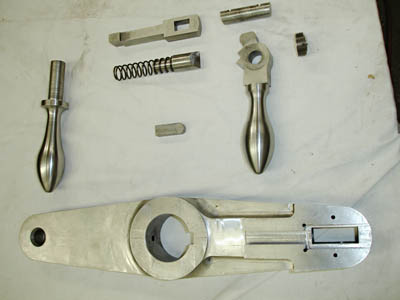
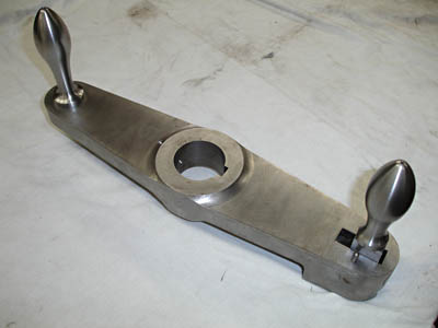
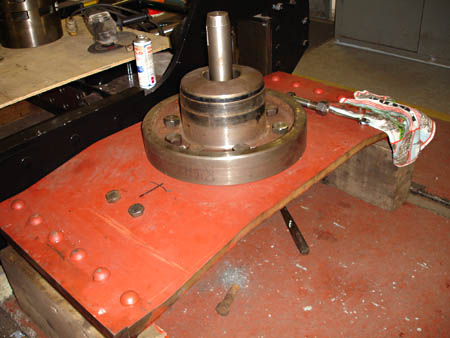 Progress continues well, with a lot of small (and not so small) parts coming together. First we have some more photos above showing the cab reverser handle, on which Fred Bailey has worked both in his workshop at home and in Atlantic House. The photo on the left is an "exploded" view of the parts which make up the reverser handle, seen complete on the right.
On the right we see the bogie stretcher and pin being assembled on 11 January.
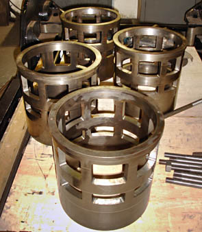
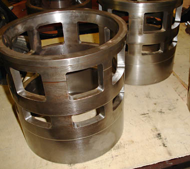
Below we see the four valve liners on 8 January - note the the stepped diameters on the outside.
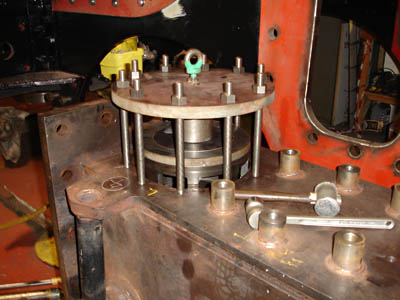
The third photo below shows one of the valve liners in position in steam chest, prior to the final pressing in, on 11 January. The ring of studs holds the reaction plate, and an enerpac hydraulic jack is between the reaction plate and the plate on the end of the valve liner. The bore of the valve chest into which the liner is to be pressed is also bored with 4 steps - each of which has to be the correct size to provide the required interference between the liner and the bore. Although the liner is about 11" long, by having these steps the total length of press fit comes down to about 1 3/4". This part of our design is copied from later practice on BR standard locos, amongst others.
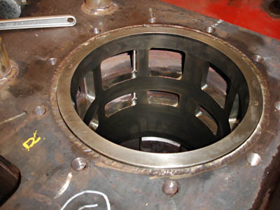
The fourth photo below shows the first liner in its final position.
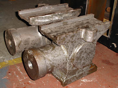
Below are seen the steel crosshead castings, received from the foundry at the end of last year. The patterns for these were seen in the September 2011 update. The mottled appearance of the surface is due to rain drops falling on the castings whilst they were being unwrapped!
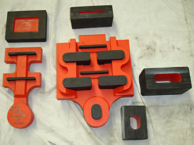
Finally we see the patterns and core boxes made for the regulator valve, which are now with the foundry.
Early March 2012
First we have a project update from Fred Bailey, and then an update on the project finances from David Jones.
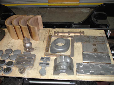
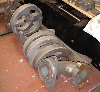
 Received from the foundry (Maybery Reliance) a month back were a large number of castings mostly from Roy Stirling's patterns.
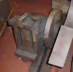
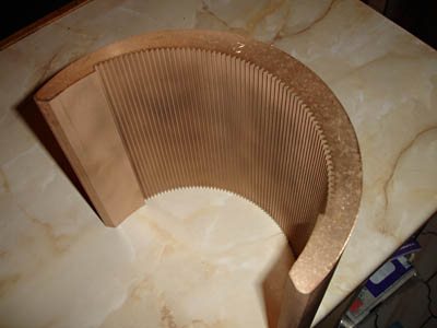
The first photo above shows the smaller parts. On the left are the new mudhole doors for the boiler. Behind them are the 4 axlebox crowns with the wire eroded teeth to hold the whitemetal linings, done by Epal Ltd of Storrington (see later for details). Just to the right of the oval mudhole doors are the regulator main valve and to its right again the pilot or first valve. Behind the regulator main valve is the whistle valve body. To the right of the first valve are two half round pieces of iron that are part of the clutch on the reversing shaft. Behind them is the blast-pipe cap and a tapered "washer" roughly square that straightens up the blastpipe. Behind that again is the bottom portion of the cab reverser scale. On the very right hand side are the crosshead slippers.
The second photo above shows some larger parts; in the front is the 'J' pipe (on top of which is bolted the regulator body up in the dome of the boiler). Behind this is the set of eight eccentric halves - one set "assembled".
The photo on the right shows the regulator body casting.
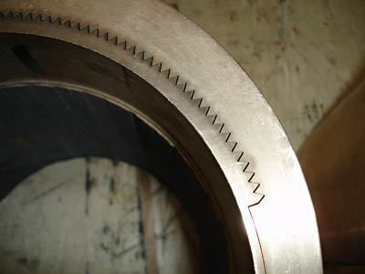
The first photo below provides a closer view of the axlebox crown.
The next shows the crown with the "scrap" part on the inside - the "cut" is produced by passing an electric current between the workpiece which is submerged in an electrolyte and a .010" diameter brass wire that runs continuously off of a large reel through the part being cut. We did not have machinery available to produce this form on site. We hope to use the same process to produce the expansion links as one can obtain excellent accuracy by doing the final operation after hardening.
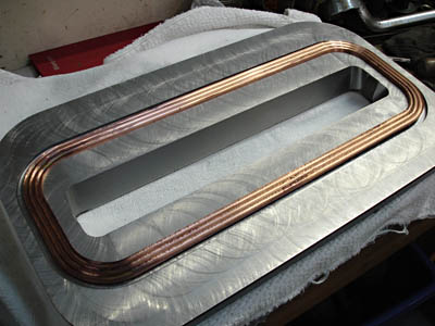
 The next photo, on the left, is our version of the "Hulburd's continuous metallic seal", CNC machined, again by Epal Ltd.
In the first week of February we received the last cylinder and the both of the liners, so hope within the next few weeks to finally assemble the cylinders and valve chests to the frames. There is of course a lot of trial fits and checks however before the final fitting.
The cab reverser has now been trial assembled and after quite a few head scratching moments works on air. Now we have to make the sheet steel cover and the cut-off scale assembly.
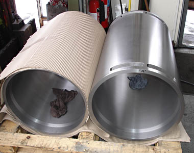
The first photo below shows the two main cylinder liners just as received, still on the forklift truck. These are quite weighty items to handle without damaging that great external finish.
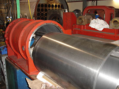
Next we see our first trial setup to work out a practical method for their assembly into the cylinders. These liners are not a press fit but are made a few 'thou smaller than the bore and are retained by a modern anaerobic adhesive; a method that has been used in the past very successfully at the Bluebell Railway.
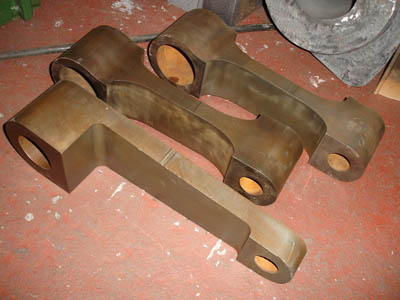 More components also arrived that week: on the right we see the lifting arms and reversing arm as received from the water-jet cutters. These are to be used as part of the fabricated weigh shaft assembly. Again forgings are now not available as a sensible option.
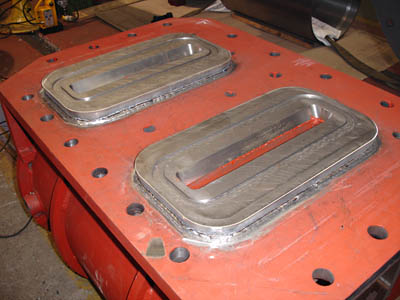
The photo below shows that by the middle of February the seal retainers had been welded to the cylinders. These retainers protrude through the apertures in the main frames and the seal is made against the faces of the valve assembly.
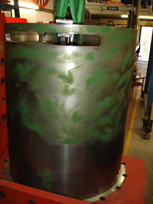

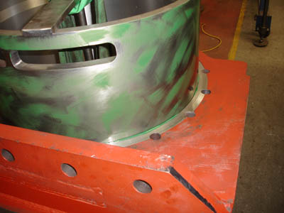
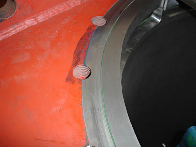
In the last couple of weeks the cylinders have been fitted with their liners.
The photo on the left shows the second of the cylinder liners, having been cleaned, degreased and coated with a high-temperature resistant Loctite, on its way into the cylinder. The bottom half of the cylinder bore was also coated with Loctite prior to this assembly.
The next photo shows the liner nearly there... the blurring of photo being due to the movement of the liner (and nervousness of photographer!).
The final photo shows the first of the two liners which had been fitted the previous week. The green line of excess Loctite in the end chamfer and in the steam port can be seen. The Loctite hardens once air is excluded and should retain and seal the liners in the cylinders themselves.
Atlantic Finances
With the delivery of the many new castings, plus liners and other machined parts, we are now facing major expenditure in the reconstruction of 'Beachy Head'. Items such as the fabricated cylinders, Hulburds seals, regulator J pipe and valve castings, eccentrics, crowns for the main wheelset axleboxes, machining the valve chest liners and further work on the main wheel crankpins have severely depleted the existing funds. Last year expenditure amounted to about £115,000, including £47,000 of labour costs, and will continue throughout 2012 as bills amounting to over £24,000 have to be paid for the Stephenson valve gear parts, water-jet cutting more of the reverser links and wire eroding the bronze bearing crowns and liners, as seen in the above engineering report.
Funding will therefore be a big challenge this year, so anyone who can assist, such as in sponsoring some of the larger items that appear on the Sponsorship List, will go a long way to making sure that progress does not slow down at this critical time where the completion of No.32424 is within sight. Our sales stand will be operating over two weekends planned for June 23/24 and the July 7/8 Model Show, and this should help with the income from secondhand books and railway artefacts.
David Jones
End of June 2012
Fred Bailey supplied this update and photos to follow on from the Project Open Days in late June.
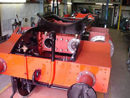
Right: The frames, sitting on the bogie and trailing wheelsets; we are still awaiting the driving wheels from Ian Riley. This view shows one cylinder cover and one valve chest cover fitted to the cylinders, as well as the anti-vacuum valves just under the smokebox saddle.
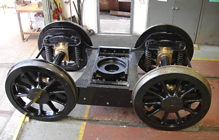
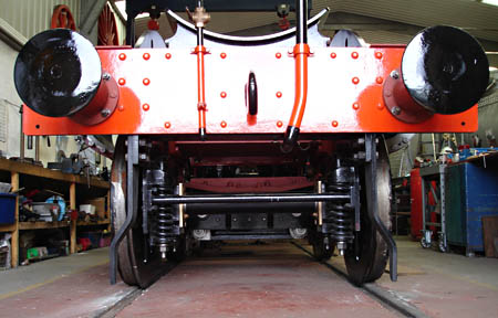
Below: A couple of weeks before, the bogie is seen, as assembled on its wheels complete with axle-boxes springs etc. The second photo shows the bogie in position under the frames from a low vantage point.
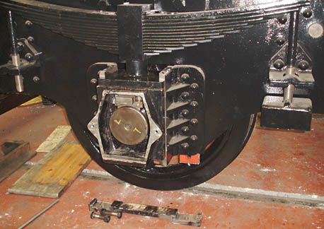
Above: The trailing wheelset installed under the mainframes, showing the bearing crown sitting on top of the axle and the keep plate that holds the crown in position. The horn stay is on the floor ready for fitting.
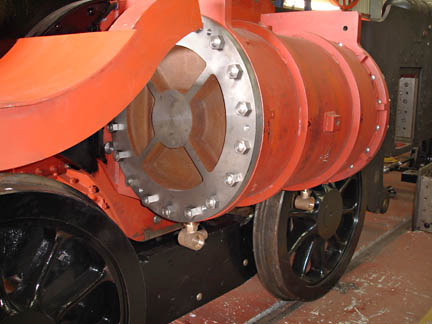
A closer view of the left hand cylinder with drain cock bodies.
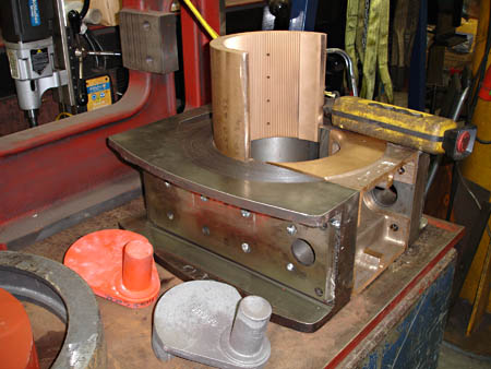
Below: An axlebox bearing crown being fitted into its axlebox. The casting (and its pattern) in the foreground are the trunnions where the lifting links (from the reverser weigh-shaft) attach to the expansion link - parts of the Stephenson valve gear.
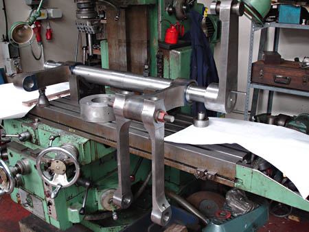
The weigh shaft itself - temporarily assembled on the milling machine table for display to our supporters and sponsors on our open day.


More recent news updates
- 2013 - Cylinders, valves, slidebars and crossheads completed - driving wheels completed - valve gear components delivered - lifting frames constructed.
- 2014 - Weigh (reversing) shaft and air-clutch fitted, axleboxes metalled, machined and fitted, wheel rotators constructed, eccentric rods, valve and reversing gear, pipework for brakes and steam heat completed, locomotive wheeled, cylinders clad and crossheads fitted.
- 2015 - Rolling Chassis completed with all motion erected. Running plates and splashers completed, along with cab sides and front.
- 2016 - Connecting and coupling rods fitted, valves set. Superheater header delivered. Revision of boiler internal pipework completed. Cab roof riveted together and fitted. Mud-hole patches welded into boiler. Flue tubes (with screw ends welded on) delivered.
- 2017 - Major progress on the boiler overhaul, and with the safety valves.
- 2018 - Boiler tubes fitted, tender made mobile, complex parts of the boiler cladding made.
- Most recent news.
Older news updates
- Background and early progress
- September 2001: Repairs to tender chassis.
- More photos of the project (1999-2002).
- March 2002: Modification of front end of tender.
- November 2004: Loco Frames ordered.
- December 2004: Bogie frame components arrive - also Feb.2005 news report.
- 2005 - Loco main frames arrive - tender frames nearly completed - start of construction of the shed.
- 2006 - Loco driving wheel castings delivered - drilling of the main frames and hornguides - building of the shed completed.
- 2007 - Main locomotive frames erected.
- 2008 - Components for the cylinders and valve chest delivered - frames riveted - forged billets for connecting and coupling rods delivered.
- 2009 - First motion parts water-jet cut from forged blanks - bogie frames assembled.
- 2010 - Cylinders and valve chests fabricated, air brake cylinders completed, bogie and trailing wheelsets completed.
- 2011 - Coupling rods and axleboxes delivered, reverser mechanism completed, crossheads cast.
Project Funding
A fund raising appeal for the cash required to complete the project was launched in 2000, and a combination of gifts made via the Bluebell Railway Trust, and standing orders set up to provide a steady income to the project have now made over a third of the total available. Whilst this has provided funding for the present work, more is going to be needed to complete the project, and the best way in which you can help is by setting up a small, regular, standing order to the Bluebell Railway Trust under Gift Aid, since this enables the Trust to reclaim the basic rate tax you have paid, and (if you are a higher rate tax-payer) enables you to reclaim some tax as well.


Return to BRPS Home Page,
to the Timetable or to Special
Events
Atlantic Project - Background - Completion and launch - Next Projects: 'Normandy' and the Adams Radial Tank
Visitor Info. -
Museum -
Trust -
Catering -
Contacts -
What's New -
Projects -
Locos -
Carriages & Wagons -
Signals -
History -
Other -
Links -
Search -
FAQ
Why not become a BRPS Member? -
Get more involved as a Volunteer
Your ideal Film/TV location?
 Photos and reports from Fred Bailey.
Page maintained by Richard Salmon
© Copyright BRPS. Privacy Policy
|
