Locomotives -
Operational Locos -
Locos under overhaul -
Locos on static display -
Locos formerly based on the Bluebell
Loco Roster -
Loco Stock List -
Loco Works News -
Join the Loco Dept
Atlantic Project - Background - Completion and launch - Next Projects: 'Normandy' and the Adams Radial Tank


Bluebell Railway Atlantic Group
2015 progress


May 2015
Fred Bailey again provides a great report on progress on the Atlantic, illustrated by detailed photos.
It is some time since I have provided you all with an update of progress on the Atlantic, and this is not because nothing has happened, but in order to go forward we have had to go slightly backwards. When building things of a mechanical nature from scratch, part of the procedure is to assemble things that require "fitting". This term is something that is a little less prevalent in these days of mass-production with computer-controlled machines and robots, but is still very much alive in the making of steam engines, just as much now as when they were the norm. Our replicas or whatever you may wish to call them are one-off hand-built units; even though a lot of the parts are made by more modern methods, the actual assembly is very much a skilled, hands-on, operation.
So basically the last few months have been spent in completing a lot of assembly and fitting jobs that have now brought the chassis up to the point of its final assembly, with all the fasteners in place and all the various retention devices (that stop the fasteners working loose with vibration) also in place but not yet finally secured. So on to the pictures.
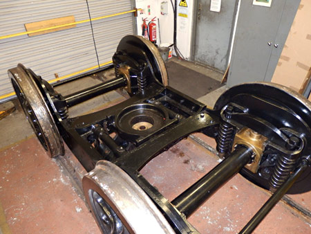
Right: The bogie appeared to be finished ages ago, but in fact a number of jobs needed completing, amongst which were the fitting of the grease nipple manifolds and grease pipes that lubricate the centre slide - part of the swing link arrangement. The finishing and fitting of the dust shields that prevent dirt and grit entering the bearings from along the axle has now also been completed. Bogies are situated in one of the messiest places on an engine, perhaps with the exception of the ashpan area. We also found one or two items that needed addressing that became obvious on our trial assembly, done previously, and these have been attended to at this stage.
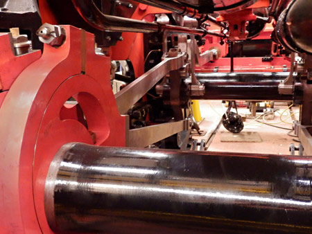
Below: Firstly we see the eccentric straps, all now white-metal lined and machined-fitted to the eccentrics themselves. Very little scraping (note one 'p') was required to get these to fit, such was the accuracy of the machining done in house by one of our team. The fit is such that, with the bolts that hold the two halves together fully tightened, the strap (without the eccentric rod attached) just revolves slowly round on its own if left in an unbalanced position.
Then we have the eccentric rods, finally coupled to the expansion links. All four eccentric rods, and the intermediate valve rods that "dodge" over the leading driving axle, have been draw-filed by hand around all of their edges to take off any imperfections or sharpness that could lead to stress-raisers in the structure of the material. This amounts to over 20 feet of edges per rod! The split taper pins can be seen in the "pivot pins" of the valve gear, just awaiting the final opening of the slit ends. Just for interest, we have found split taper pins difficult or impossible to obtain recently, so we have had the slits wire eroded in the pins. It is only a 0.010" slit, so hacksaw cuts are out of the question. I have for odd individual ones done the job on my milling machine using a 0.010" slitting saw.
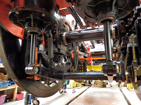
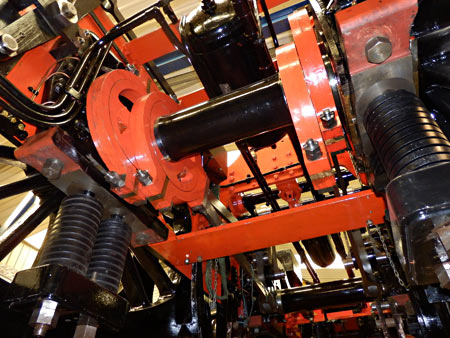
The next view below shows the two locomotive Westinghouse brake cylinders now finally assembled with their pistons and seals, then coupled up to the brake shaft. A member of our team has produced a test rig to check the operation of the various component parts of the vacuum/air system, and this will be described in more detail in a later update. Also just visible in the photograph are the leaf springs on the leading driving axle, this being the first time these parts have been assembled. They are "interesting" to fit, (read awkward!) even with the chassis raised as shown. The orange Carver clamps were keeping the rubber shock pads in position until the chassis was lowered on to its wheels.
A further view, similar to the previous one, shows the coil springs fitted to the main driving axle. As the axleboxes are sitting on the horn stays it can be seen that the springs were not in contact with the undersides of them. All that changed once the wheels touched the floor. Further work carried out at this stage was the final installation and fitting up of the control linkages to the 7 drain cocks. Even with the chassis raised up a lot of kneeling and crawling around on the concrete floor has been required and at least two of us are suffering with some knee and leg problems - we are not getting any younger!
 Enough of the undersides; what has happened "up top"?
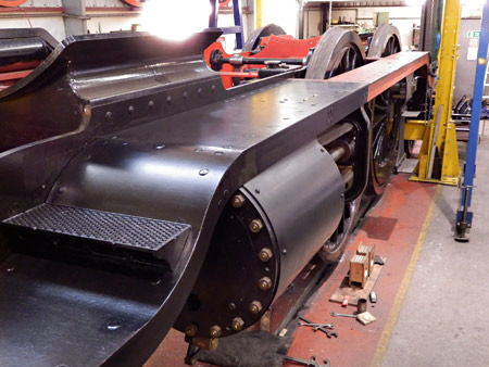
Left: The running plates are now complete as far back as the cab front. This was a difficult job due to the weight of the parts, and on the side nearer our outside wall, with more limited accessibility. In this view can be seen the front steps, produced using polystyrene "disposable" patterns straight from the 3D drawings. The plates are 3/8" thick steel and the valences 5"x3"x1/2" angle. We had to fabricate the curved portions of this, as section roller companies of today were unable to do the radii we required in the size of material we were using - no problem seemingly for the "Brighton" in 1910! Most holes were laser cut in the plates, but all had to be drilled through 21/32" diameter (not Black & Decker sizes) and then countersunk. This was especially tricky even with a magnetic based drill when going around the curved parts. The countersunk bolts were ordered specially for the project and then in order to make the engine more maintenance-friendly (and yet keeping the appearance of rivets) each bolt has had its head re-machined.
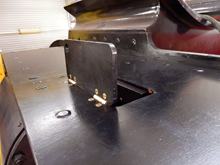
Below: Just behind the cylinders on both sides of the engine there is a "hidden" door that allows access to a 3-feed oilbox underneath. All that is visible is the tops of the hinges and a hole for one's finger to lift the lid. A nice touch not often seen in photos, but on the original drawings.
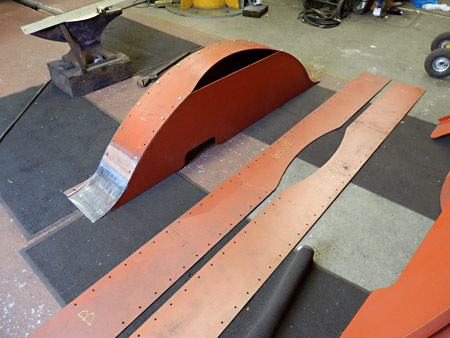
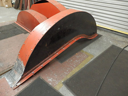
The next photograph shows the first of the leading splashers assembled with temporary bolts and now ready for riveting. On the floor are the tops of the trailing splashers before we put them through our bending rolls to form the shaped top and reverse-rolled front end. Even after rolling to shape there is a lot of tricky work entailed in getting the fit just right, sometimes requiring the use of heat and mallets. "Bodywork" for steam engines is a bit heavier than that for cars.
Below that is a later view, showing the rear splashers assembled with temporary bolts.
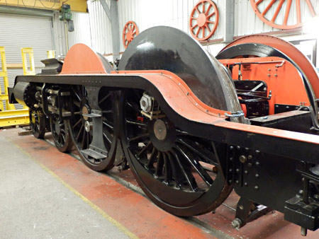
Finally we see a view looking forward on 2 April, which shows the chassis down on its wheels with the splasher fronts in position, as was required to get the angles that join the splasher fronts to the running plates drilled and countersunk ready for the bolts. Prior to fitting the splashers, once all riveted together, we have to drill for the prominent oil boxes that are located on the splasher tops and also for the nameplates. Getting to these fixings once the splashers are fitted to the running plates will be almost impossible.
On our Open Days, on 13 & 14 June, those of you that are able to visit will be able to see this progress for yourselves. As usual our sales stand will be open and members of the team will be available to answer questions or explain any items of interest.
June 2015
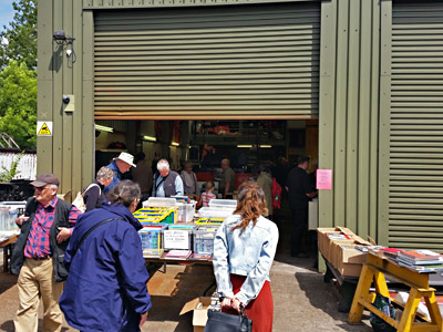
June 13-14 was our annual "Open House" event, and these photos show what was to be seen by our supporters and subscribers.
The sales stand, and access to view, should (all being well) next be available on Sunday June 28, as part of the Bluebell's Model Railway Weekend
The photo on the right is from Martin Lawrence, and the next two below are from Fred Bailey.
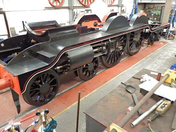
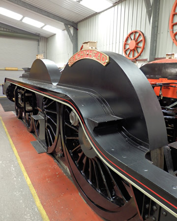
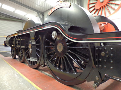
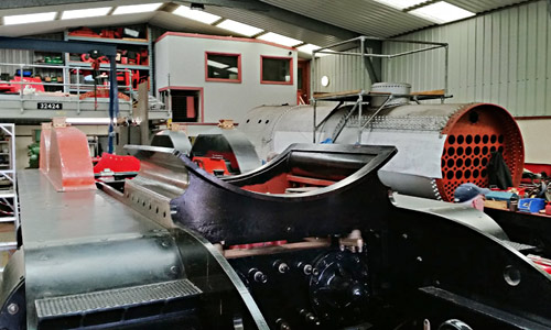
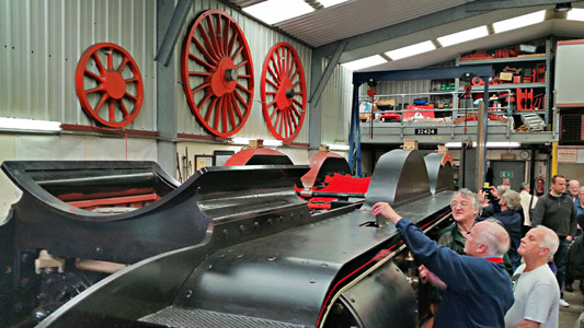

The next photo, above, is another from Fred Bailey. The other, showing both the frames and boiler, is from Martin Lawrence, as is that on the left, where David Jones is seen showing visitors the door giving access to the oilbox beneath the running plate.
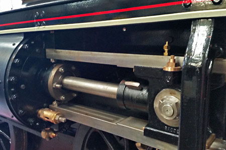
Martin's photo below shows the cylinder, with the piston rod attached to the crosshead.
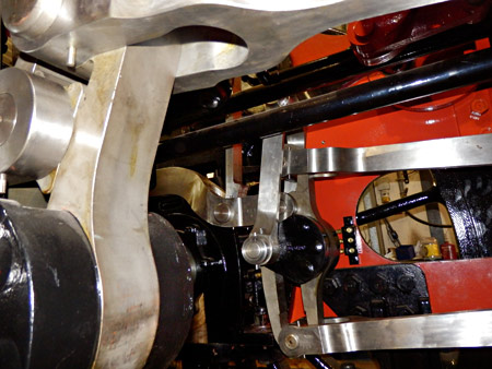
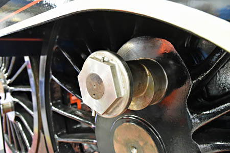
Brian Lacey's photo below shows the last major items to be fitted to the rolling chassis to be the connecting and coupling rods. The unusual eccentric crankpin on the driven wheels allows the throw of the coupling rods to be reduced (thereby reducing balancing needs and hammerblow to the track) whist accommodating the full stroke of the pistons.
October 2015
The Atlantic House sales stand, and access to view the project, will be among the attractions available over the weekend of 31 October & 1 November for Giants of Steam.
Our thanks to Fred Bailey for this report and the photos.
When building a new locomotive there are unfortunately times when no large impressive parts arrive on site or are bolted on, but work progresses never-the-less, completing a lot of the smaller "detailing" parts without which the whole cannot function or would look incomplete. We have been through a long spell of this, but the following should hopefully show what is happening.
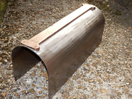
The chassis is sitting on its wheels with the wheel rotators in position ready for valve setting, but the cab reverser needs to be finally assembled with all of its internal parts fitted, and the whole firmly bolted to the pedestal which just happens to be part of the cab itself. This photo shows the cover that fits over the reverser proper and carries the cut-off indicator, the bottom half of which is riveted and sweated to it ready to receive the indicator scale itself.
LB&SCR locos built at Brighton are liberally supplied with rivets. Our cab is made much in that traditional manner. Any welding is being kept to an absolute minimum to prevent distortion problems and to keep within the brief of it being a reconstruction of the original, especially where it can be seen.
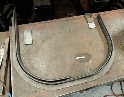
One place where we could not avoid welding was in the making of the two cab look out beadings. Originally this was an "off the shelf" drawn 'T' section - just bend to shape drill and rivet! Not today. This one part has had to be made from 6 separate pieces, as seen in the photo below. Two lengths of 'D' section steel, two lengths of flat to which the D shaped parts were welded plus the two end pieces that take the handrails. The whole lot then ground, filed and emery papered to get a good finish.
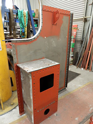
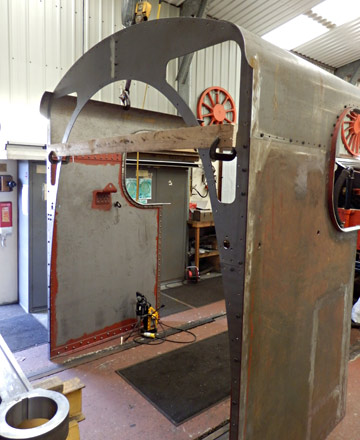

Here we have the first trial assembly of the cab sides, upper sides (that join to the roof) and the cab front sheets. New brackets have been made at this stage to take the Gresham and Craven Vacuum brake ejector on the driver's side and the Detroit sight feed lubricator on the Fireman's side. Although being fitted earlier than expected, it is easier to rivet them on now rather than later.
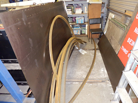
Talking of rivets, our cab roof kit is to be seen below. There are 438 rivets in the cab roof alone! The cab roof itself has feather edge 'D' section beading across the top front and back, plus two strips of 3" x 3/8" flat steel strip going across side to side, then two 'T' sections (now not obtainable from stock, so requiring fabrication) also going from side to side, an angle to fix the roof to the cab front, and to finish another angle running around three sides as a rain gutter. This is why a proper reconstruction takes time, but all this is in full view from the foot-bridges and even from the platforms.
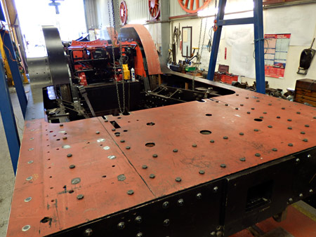
To prepare for the fitting of the cab the three plates making up the cab under-floor have now had various holes cut through them ready to take the various pipes that eventually find there way up into the cab. These include those for the air and vacuum brake plus those for the injectors both steam and delivery. These floor plates have now also been drilled and countersunk where required and finally bolted down to the frames.
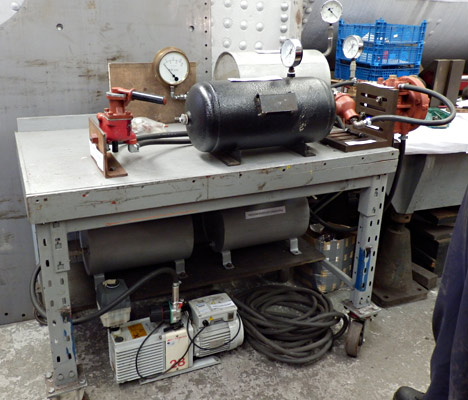 A small test rig has been assembled from various parts that we had about us based generally on the Westinghouse Brake and Signal Company test procedures so that the various parts that we will be fitting can be checked accurately for proper function, prior to us fixing them on the engine. All parts were found to function according to specification, so they have now been installed in their final positions.
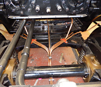
The "Brighton" never seemed to do things the same as other Companies. Most locomotives have bits of pipe coming from the drain cocks that head forwards and are clipped to the front steps or something similar. On the Atlantics and the J tanks they start by going backwards before curving around between the bogie and the frame stretcher above, then diving down behind the leading bogie axle before pointing out under the coupling. All 6 of them (on the original loco) and 7 the new one. Things will become crowded later in this area once the Westinghouse pump and its various pipes and fittings are installed.
The next two photos show the rear decorative cylinder cover shrouds (for want of a better term). These were spun to form the outside then pressed to match to the gland. These were bought in as basic spun items and then individually hand fitted to the job. Some things are not in our normal "comfort zone" so buying in that expertise although appearing to be expensive is in fact an economical option. The Company that made these for us did a first rate job although the four covers cost a little more today than the complete locomotive with tender did in 1911! The fitting of the rear one next to the frames was "fun" as we had to remove the splasher that covers the rear bogie wheel to get it in. The Atlantics must have been almost as much a fitter's nightmare as an original Bulleid Pacific!
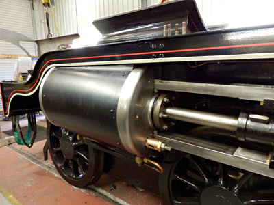
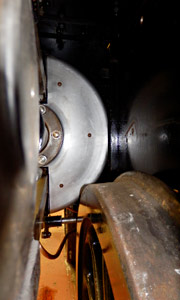
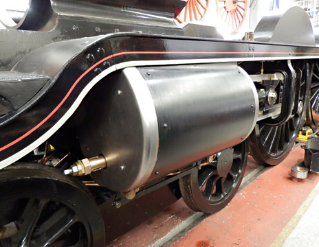
 On the left we see the distinctive front cover. When built these had a piston tail rod housing protruding through them and the covers were kept burnished. Some had a patch plate to hide the hole where this was when the tailrods were removed and others had new covers fitted, ours being like the latter ones. In later days these covers were painted, as ours will be. With locos being left outside not in use for periods of time in excess of what would have been normal in years gone by this painting of these covers should help in keeping them from deteriorating too quickly.
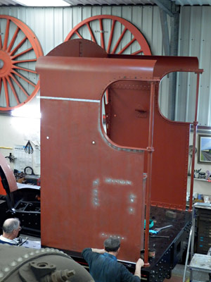
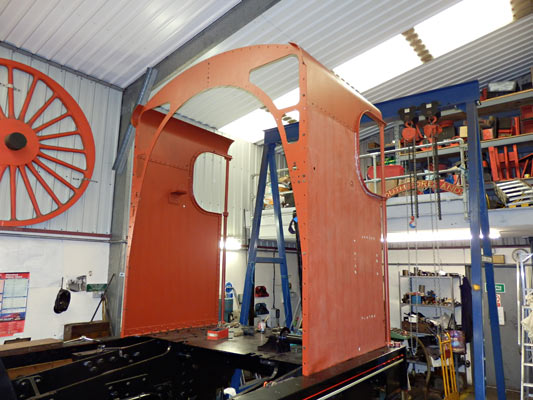
The photos below show the basic cab complete with handrails mounted up on the rear foot-plating. As can be seen painting is also now being undertaken at least as far as the application of a couple of undercoats. A few more holes need to go into the sides especially on the fireman's side for his seat so top coating would be a little premature. The Atlantics gave the fireman time to "enjoy" the ride, so he got a seat whereas the drivers only had a shed made rough and ready item that fitted above the reverser.
The front spectacle plates are made removable (the original ones were riveted) to allow easier access for the installation of the boiler. (In due course). Work is also now in hand producing the patterns for the spectacle plate windows.


More recent news updates
- 2016 - Connecting and coupling rods fitted, valves set, Superheater header delivered, Revision of boiler internal pipework completed, Cab roof riveted together and fitted, Mud-hole patches welded into boiler, Flue tubes (with screw ends welded on) delivered.
- 2017 - Major progress on the boiler overhaul, and with the safety valves.
- 2018 - Boiler tubes fitted, tender made mobile, complex parts of the boiler cladding made.
- Most recent news.
Older news updates
- Background and early progress
- September 2001: Repairs to tender chassis.
- More photos of the project (1999-2002).
- March 2002: Modification of front end of tender.
- November 2004: Loco Frames ordered.
- December 2004: Bogie frame components arrive - also Feb.2005 news report.
- 2005 - Loco main frames arrive - tender frames nearly completed - start of construction of the shed.
- 2006 - Loco driving wheel castings delivered - drilling of the main frames and hornguides - building of the shed completed.
- 2007 - Main locomotive frames erected.
- 2008 - Components for the cylinders and valve chest delivered - frames riveted - forged billets for connecting and coupling rods delivered.
- 2009 - First motion parts water-jet cut from forged blanks - bogie frames assembled.
- 2010 - Cylinders and valve chests fabricated, air brake cylinders completed, bogie and trailing wheelsets completed.
- 2011 - Coupling rods and axleboxes delivered, reverser mechanism completed, crossheads cast.
- 2012 - Valve and cylinder liners fitted - lifting and reversing arms and axlebox crowns delivered - castings for mudhole doors, regulator and whistle valves, reversing shaft clutch, blast-pipe cap, crosshead slippers, 'J' pipe and eight eccentric halves received - Bogie and trailing axle now support the frames - Valve chest and cylinders fitted to frames, covers fitted, and pressure tested.
- 2013 - Cylinders, valves, slidebars and crossheads completed - driving wheels completed - valve gear components delivered - lifting frames constructed.
- 2014 - Weigh (reversing) shaft and air-clutch fitted, axleboxes metalled, machined and fitted, wheel rotators constructed, eccentric rods, valve and reversing gear, pipework for brakes and steam heat completed, locomotive wheeled, cylinders clad and crossheads fitted.
Project Funding
A fund raising appeal for the cash required to complete the project was launched in 2000, and a combination of gifts made via the Bluebell Railway Trust, and standing orders set up to provide a steady income to the project have now made over a third of the total available. Whilst this has provided funding for the present work, more is going to be needed to complete the project, and the best way in which you can help is by setting up a small, regular, standing order to the Bluebell Railway Trust under Gift Aid, since this enables the Trust to reclaim the basic rate tax you have paid, and (if you are a higher rate tax-payer) enables you to reclaim some tax as well.


Return to BRPS Home Page,
to the Timetable or to Special
Events
Atlantic Project - Background - Completion and launch - Next Projects: 'Normandy' and the Adams Radial Tank
Visitor Info. -
Museum -
Trust -
Catering -
Contacts -
What's New -
Projects -
Locos -
Carriages & Wagons -
Signals -
History -
Other -
Links -
Search -
FAQ
Why not become a BRPS Member? -
Get more involved as a Volunteer
Your ideal Film/TV location?
 Photos and reports from Fred Bailey. Additional photos © Martin Lawrence and Brian Lacey.
Page maintained by Richard Salmon
© Copyright BRPS. Privacy Policy
|
