Locomotives -
Operational Locos -
Locos under overhaul -
Locos on static display -
Locos formerly based on the Bluebell
Loco Roster -
Loco Stock List -
Loco Works News -
Join the Loco Dept
Atlantic Project - Background - Completion and launch - Next Projects: 'Normandy' and the Adams Radial Tank


Bluebell Railway Atlantic Group
2016 progress


January 2016
Our thanks to Fred Bailey for this report and the photos.
First of all I must explain that the lack of frequent updates here is not due to there being nothing happening. Rather, we are making a lot of progress, but it is difficult to produce photographs showing it. For instance there have been further runs of small copper pipe installed between the frames to take steam to the sanders. We are also now installing the injectors under the cab, together with the rest of the piping for the vacuum brakes, the air brakes and the steam heating. All this becomes an interesting lot of knitting! A lot of the work is therefore of a more hidden nature, but the chassis is now very near to completion and work will very soon be starting on the boiler. Various work is in progress to enable that work to start as can be seen in one or two of the pictures. On order are pre-shaped sections of boiler plate to fill in the holes above the foundation ring where we removed the sections of boiler containing the corroded areas around the mud hole doors. The drawings have been completed for all of the ashpan and the damper assembly, but the plates for this will not be ordered just yet.
So, on to the pictures:
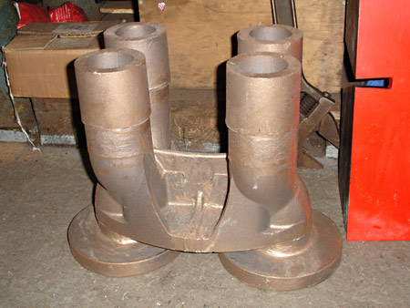
To the right and below left: Just delivered from Premier Patterns is the casting for the double Ramsbottom Safety Valves. All Brighton Atlantics had these to the end of their lives with, I think, one H1 exception. Unlike the GNR/LNER locomotives they were not fitted with Ross Pop Valves. Our casting is for the twin Ramsbottom type with all of the critical working parts produced to the original designs.
Also received at this time is one of the backhead fittings. This is a casting (seen in the other two photos below) that combines the functions of the injector steam valve and the boiler feed non-return valve body. The right hand version is to follow shortly. These are to fit to our ex LNER boiler, but the "Brighton" used very similar designs on their Atlantics. Various changes took place over the years, but we have based ours on their appearance in the later days.
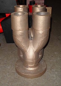
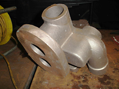
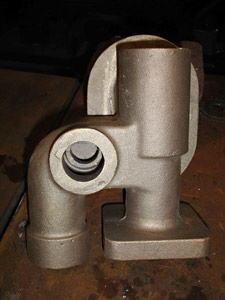
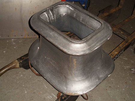
The final part from Premier Patterns, seen above on the left, is the decorative shroud that fits around the safey valves and partially hides them from view. This time the casting is in Sphericular graphite iron, a stronger version of standard cast iron.
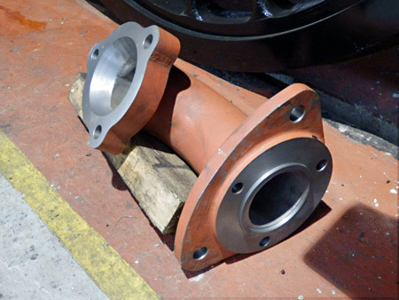
On the right, above, is the machined 'J' pipe. This fits inside the dome, and the regulator (also being machined in house) sits on the top of it. Another step towards the boiler.
Now, onto the loco itself. We have now fitted the connecting rods to the engine and the driving wheels are sitting on the rollers. The reverser is complete and is bolted firmly in the cab and the latter in turn is finally bolted down to the chassis. We are now about to complete the valve setting. A preliminary run through of this has got things close but we need to run over it again as a check before fitting all the covers etc. back on the front end. We have found that we can turn the engine over using a simple ratchet spanner with a short tube on it. Even with everything coupled up one can slowly turn it over one handed. The exception to this is when one comes to the part of the rotation when one is lifting both of the balance weights at the same time - then it makes one blow a little! As soon as valve setting is complete we will fit the coupling rods and remove the rotators.
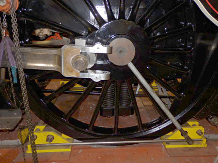
Below we are turning the driving wheels using the rotators. Working in conjunction with a small chain hoist on the connecting rod we can then "feed" the crankpin into the front half of the big end bearing. The rear half bearing is then pushed into position followed by the glut plate, the wedge and the centre block and its tapered bolt.
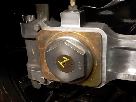
The next photo shows the assembled big end on the other side of the engine. The head of the bolt at the left hand end may not actually fit tight to the top of the big end strap as the bolt shank and the hole through both sides of the strap and the centre block are both a continuous matching taper. It will go in a bit further once we have fully driven it in.
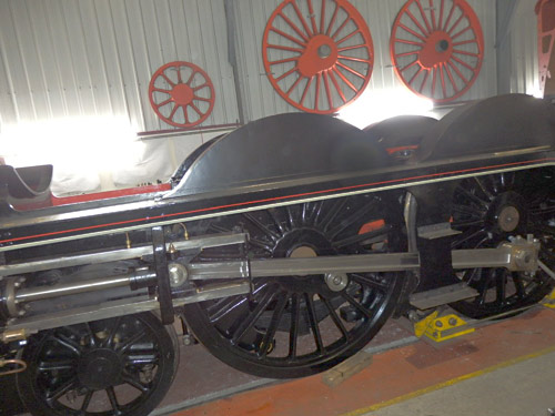

It is not easy to get an over-all picture with the limited room available in Atlantic House", but here, on the left, is the centre of the chassis with the connecting rod in place.
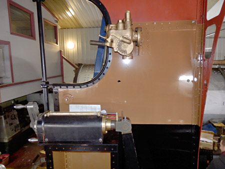
Below we see the finally assembled reverser mounted in the cab, with the Vacuum Brake Ejector mounted temporarily above it in order to start piping up both it and the Westinghouse Air Brake valve, that is not yet in position. All this needs to be done at this stage as there is still a lot of piping to go in beneath the cab, and between the frames.
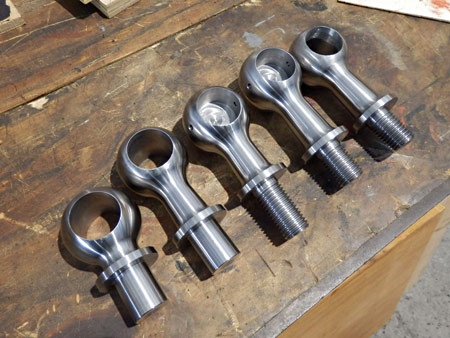
The final photo shows a selection of the handrail knobs, recently completed by Epal Ltd. of Storrington. There are 22 handrail knobs in total with something like 8 variations.
March 2016
A significant set of photos, with work moving on to the boiler, with thanks to Fred Bailey.
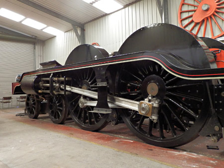
The chassis is now getting close to completion with the valves now set, the valve chest covers re-fitted and the coupling and connecting rods erected. We have now removed the rollers from under the driving wheels as they are now not required. So, we now swing over to work on the boiler. First of all we have had to make some room around it to get space to work, so the large marking out table ex Eastleigh loco works and weighing 4 tons or so has had to be removed.
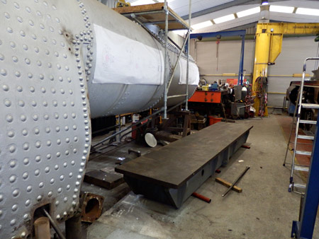
The photo on the right shows the large marking out table, alongside the boiler, cleared of parts and rubbish, resting on pipe rollers ready to be pinch-barred to the doors.
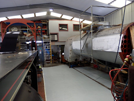
The first photo below shows that, once the marking out table was removed, we cleaned and painted the floor ready to get to grips with the boiler.
With a bit more room, this view became available showing the chassis with the coupling and connecting rods all assembled.
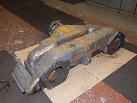
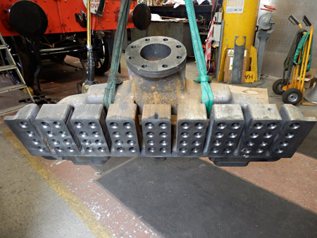
As of Wednesday 9 March we received the superheater header, in SG iron, cast, machined and pressure tested from Premier Patterns and Castings, as seen in the two photos above, the second of which shows the underside with all the coned holes ready to take the superheater elements.
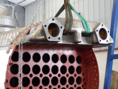
We carried out a "loose" trial fitting the following day just to check on the practicalities of its fit to the boiler and within the smokebox. As can be seen below it over-sails the edges of the boiler barrel by some way, but this will still fit within the smokebox which is about 5" larger in diameter than the boiler.
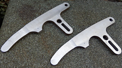
Finally we see the two safety valve easing levers, which were initially water-cut to profile and then finished by various milling processes in house.
Work is also well advanced on the regulator valve and is about to start on the safety valve columns themselves. Quite a tricky job again.
June 2016
Another few months on - report and photos with thanks to Fred Bailey.
It has been a little while since we have updated this site with our progress so I thought it about time I updated things a little. There are all sorts of things on order and happening as I write, but for those I have no photographs. At present we have on order the castings for the fire-hole door together with those for its hinges. The other parts for this are laser or water-jet cut and are in stock as I write, but obviously they all need further engineering work carrying out on them to make them useable. The "Brighton" fire-hole door is like most others not as simple as it might appear there being at least 20 components required to make up the assembly. Also on order at this time is the large cross member that spans the firebox to support the firebars. At present I am still working on finding the correct iron specification for the latter. There are 160 of them needed to make up the grate.
 With our sub-contract machinist company in Storrington are the window frames for the cab spectacle plate windows. Due to their odd shape they lend themselves to being CNC milled from the basic castings. Glass for these will be ordered shortly - not picture glass though! Also there are the "bottle ends" that will be welded to the superheater flues. These all need to be machined inside and out to match the flue tube thickness and need threading at one end to suit the threads in the copper tube-plate in the firebox. All the tubes (134 of them) and the Superheater flues (32 of those) are on order with delivery expected before September.
Now to the bits I do have photos:
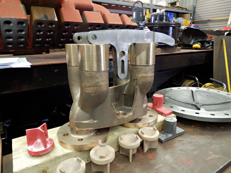
The photo on the right shows the safety valve casting now finish machined in house. Sitting on the top of them are the two easing levers and in front are the raw castings for the valves themselves.
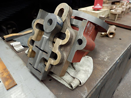
Below we see the main regulator body and the small and large valves that act upon it, again machined in house. When fitted in position the slide valves operate vertically. It is almost upside down sitting on the bench.
Next is the underside of the inner dome cover. This was cast from a polyurethane pattern and supplied to us fully machined. It provides access to the regulator valves which are fitted within the dome.
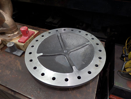
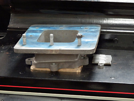
 The lower blast-pipe is seen on the left. This component is bolted down to the flange on the top of the valve chest with a tapered bronze washer interposed between the two flanges to set the top face of this casting level. The result is that the blastpipe proper should be vertical and centred under the chimney. This was cast from a normal pattern and machined in Atlantic House. When finally fitted all of this will be forgotten and under a layer of heat resisting concrete.
We are currently awaiting the cast and fully machined upper blastpipe.
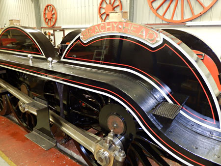
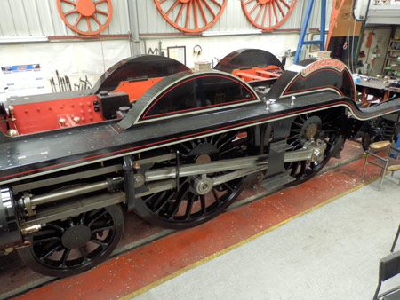
For our open day in June which we arranged for our supporters, subscribers and sponsors, we played a bit to the gallery by getting the splashers properly painted, lined and varnished with the nameplate and axle-box lubricators attached. These two pictures hopefully show how nicely they worked up. Interesting to note we found that as far as we could tell each of the H2s in BR days were lined out differently.
August 2016
We are pleased to be able to present this, another of our regular updates, from Fred Bailey.
 With the chassis all but complete we are now of course working on the boiler and its various ancillary parts. As might be expected, a lot of this is far from spectacular and is quite slow work, some of it being heavy and some of it quite tricky. I hope you will all understand if this report does not have lots of "wow" factor but unfortunately most of the construction of an engine is very mundane and requires a lot of tenacity from the build team to work through these times, and patience from our sponsors and supporters eager to see progress.
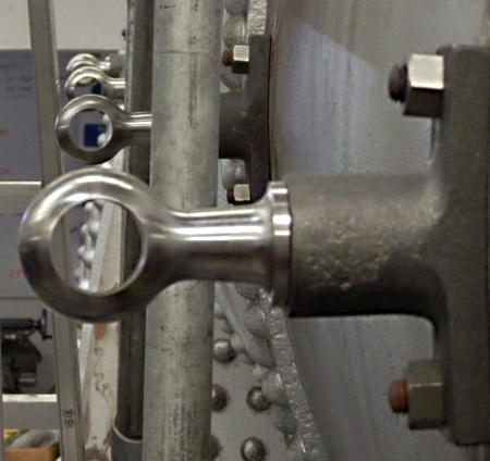
Believe it or not the handrail knobs on most locomotive boilers are bolted into the pressure vessel itself, rather than to the support crinolins for the sheet metal lagging. The result of this is that we have to fit the stand-offs for the handrail knobs before we can fill the boiler with water. This picture shows the handrail knobs temporarily fitted in the stand-offs that are in turn fastened into the boiler barrel. Needless to say, the scaffolding and ladder for access to the dome will be removed before the handrails themselves are fitted! The handrails are hollow as they contain the operating rods for the blower steam valve on the left side of the engine, and the Westinghouse Pump steam valve on the right side. To achieve this the standoffs on the firebox are of a different design to those on the boiler barrel and even these latter items are of two differing lengths due to the differences in size of the rings of the boiler.
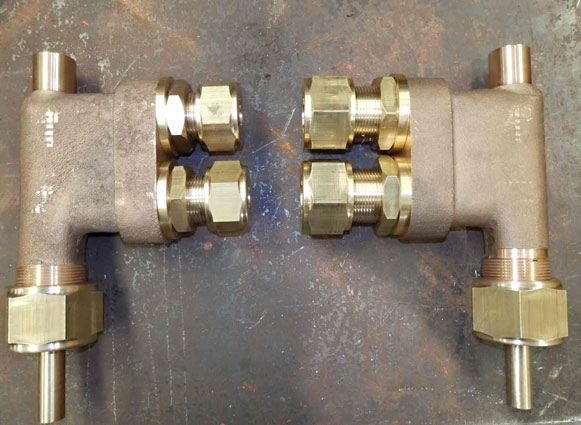
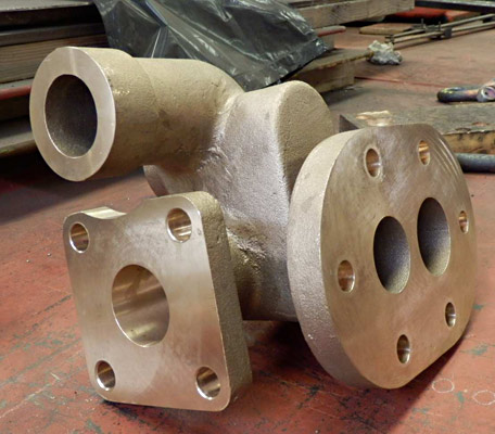
Below we see the blower steam valve and the Westinghouse Pump steam valve, which are now both almost complete, as produced in house by one of our skilled volunteers. The blower valve has the smaller pipe connections. Both are fitted to the sides of the smoke-box in line with the handrails. The lock nuts on the two pipe connections retain them in position on the smokebox.
The next photograph shows the two rings that build up the outside of the barrel to meet the smoke-box. The original "Brighton" engines had a single piece of 21/2" wide by 23/8" thick steel bar wrapped around the boiler to achieve this. (The original piece weighed about 353.5 lb - 160 Kg for the younger folks). We have however an ex LNER boiler that has a double row of rivet holes left over from the fixing of an angle iron front ring that fitted to the smoke-box, so the wide but thinner inner ring is fixed using the holes nearest the tubeplate (so blocking them with bolts) and the narrower, but thicker outer ring is fitted using the row of bolt holes nearest the end of the boiler barrel. Although a little more work it made the pieces slightly more manageable and allowed us to use metric thicknesses of material without needing any machining operations.
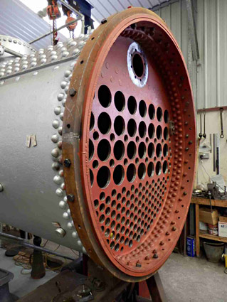
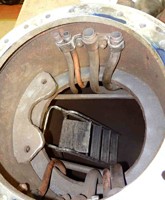
 The view on the left is looking straight down inside the inner dome and shows the 8 pipes that collect the steam for all of the boiler ancillaries. The rough looking bracket with the two holes is of LNER design and manufacture to which we will be fitting our main steam pipe and regulator valve. You will note the step ladder inside to allow access to the inside of the barrel. Four of these pipes are completely new and the others have needed to be re-routed because the LNER engines had a small manifold above the boiler back-head for the smaller ancillaries, but the "Brighton" locos did not. This extra work has been produced by our replicating as nearly as possible the back-head layout of the original Brighton Atlantics and we hope it will be appreciated in due course. It has kept one of our more senior members of our workforce confined inside the boiler for some quite extended periods of time. Not a comfortable place to work as it is just too small to allow one to straighten up. I know, I have been in there myself (and struggled the last time to get back out!! Must loose some weight!)
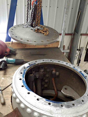
 Next we have the start of the final facing of the flange on top of the inner dome ready for the fitting of the inner dome cover. This was first carried out by offhand angle grinding and then finished to a marking blue witness by hand filing and scraping of the flange. The inner dome cover (in the photo) being just behind and above, hanging on the hook of the hoist, so it can be try fitted between each session of filing or scraping. Although the flange was quite poor both for flatness and for pitting due to its long time exposed to the elements we decided to do the work by hand even though we could have hired a flange facing machine. By the time we had set up this machine accurately and with the uncertainty of the effect to the surface finish with the tool cutting across the stud holes, we are sure that in the end the method chosen was more cost efficient and probably quicker. The hire fees were daily plus packing and carriage charges both ways so this could have run to a considerable sum if any snags were met.
The first picture below is of one of the injector combined clack and steam valve bodies at the end of the first machining operations.
Now at last we have received the small tubes for the boiler. The 32 large flues and the machined bottle ends that are welded to them are away at present for welding by a specialist and will be due back before long.
November 2016
Fred Bailey sent through the update below a few weeks ago; apologies for the delay in publishing it.
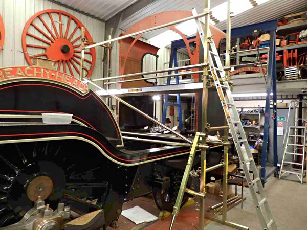 We are getting to the point where we need to work at height, so have now invested in new industry standard tower scaffolding in order to be safe in so doing. Here is a small selection assembled to allow us access to the top of the cab front to mark off the holes onto the angle iron that gets riveted to the cab roof and bolted to the spectacle plates. In due course more of this will be erected to down both sides of the cab as well as across the cab front in preparation for fitting the cab roof to the cab sides.
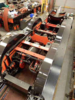
While up in the roof it allows a nice shot (below) of the chassis to be taken. Apologies for the lack of gloss on the splashers - dust!
The cab roof is in two parts. The middle photo is the small rear part that was made removable to allow access for the chains from the breakdown cranes or those in the main works to get at the drag beam. The cab roof projects some way past the drag beam.
How we love the "Brighton" cab roof. There are 315, 3/8" rivets in this piece alone. The chain hoist and strops allow us to angle the roof to get the rivets square to the plate.
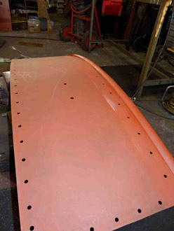
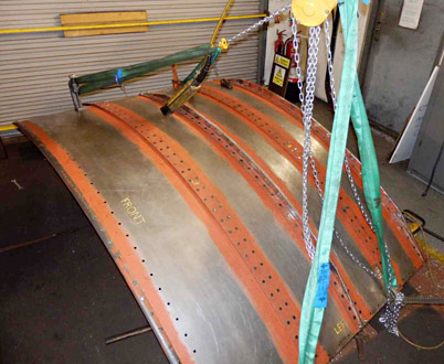
Next below is an underside view with a rivet sitting in the snap ready to flatten down with the rivet gun. All of these rivets were gunned in cold, together with a photo of one of our team in the act of making a lot of noise!
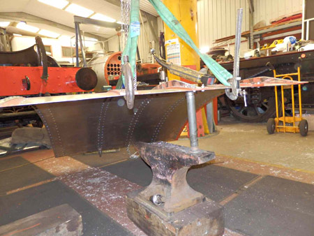
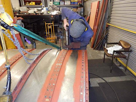
Below we have the larger part of the cab roof in position, ready to adjust to the sides and drill through for the fixings. There is a shorter section to add to the rear later on.
The final photo, with holes now spotted through and a few bolts fitted temporarily to hold things in place prior to fitting the right hand side in a similar fashion.
Other news in brief: We now have a sub-contract coded welder working on the patches in the boiler at long last. The air reservoir that powers the cab reverser is being welded by the same company. The handrail knobs shown in the last update are now properly fitted with their taper pins to the stand-offs on the boiler. Not as easy a job as one would think. It is best done in situ using a dummy length of handrail tubing to get the orientation of them correct and in line.
December 2016
Fred Bailey supplies this intermediate update to finish off 2016. In addition David Jones has just provided an updated component sponsorship list, since we're pleased to say that quite a few items have found sponsors in the last few weeks.
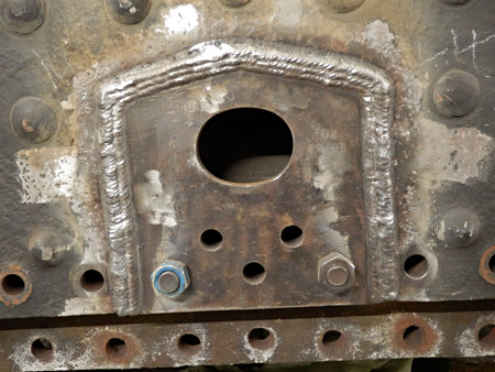 As we end the year work is now well under way on the welding of the patches required to replace the areas around the old mud hole doors that had corroded in the years when it was out of use. Once this is completed and inspected then we will be involved in riveting the bottom row of foundation ring rivets, prior to removing and replacing the row above. This is a normal procedure at the time of a ten year boiler overhaul, as these rivets tend to suffer from the damp ashes and heat.
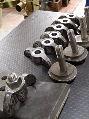
To go with this boiler work we have now made the mud doors (photo below) which are fitted (i.e. adjusted to fit accurately) into the new sections of plate, plus the large inspection doors that are on either side of the firebox above the level of the inner firebox crown sheet. These latter not yet photographed.
Also not photographed is the J-pipe which supports the regulator and connects the main steam pipe to the front tube plate, which is now bolted up finally in its position in the dome.
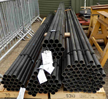
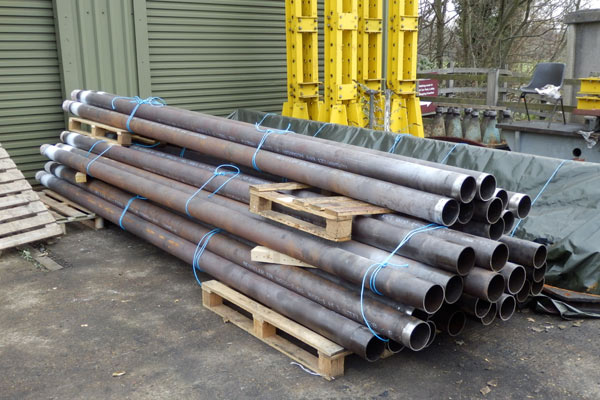
In the second photo below are the 32 off, 16 foot long, 51/4" outside diameter flue tubes as they were delivered. The ends near to the roller shutter door are reduced in diameter and are threaded to screw into the firebox tubeplate. These threaded ends were welded to the main flues by a sub-contract coded welder. These have had their threads protected and been covered with a tarpaulin similar to the small tubes that are seen under their tarpaulin behind.
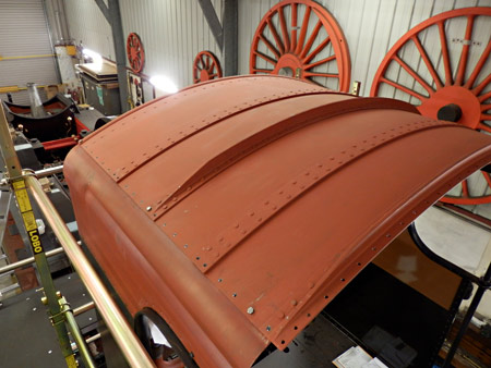
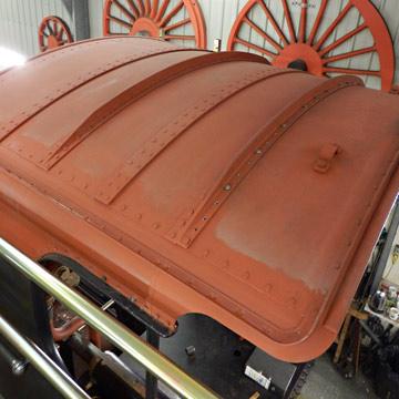
The top side of the cab roof is seen below, with the back removable section now in place, but without all the bolts securing it just yet.
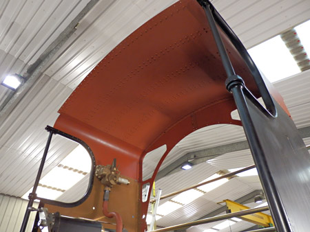
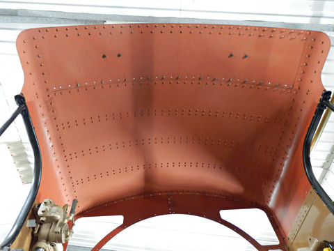
The inside of the cab roof is seen next, with all the snap heads of the rivets on show; there are about 438 of them.
To conclude, Fred would like to ask if anyone out there has a source of plain mild steel round head and countersunk screws 3/8" Whitworth by 1" and 11/4" long at a sensible price? We need about 200 of each type and most sources seem to be profiteering!


More recent news updates
- 2017 - Major progress on the boiler overhaul, and with the safety valves.
- 2018 - Boiler tubes fitted, tender made mobile, complex parts of the boiler cladding made.
- Most recent news.
Older news updates
- Background and early progress
- September 2001: Repairs to tender chassis.
- More photos of the project (1999-2002).
- March 2002: Modification of front end of tender.
- November 2004: Loco Frames ordered.
- December 2004: Bogie frame components arrive - also Feb.2005 news report.
- 2005 - Loco main frames arrive - tender frames nearly completed - start of construction of the shed.
- 2006 - Loco driving wheel castings delivered - drilling of the main frames and hornguides - building of the shed completed.
- 2007 - Main locomotive frames erected.
- 2008 - Components for the cylinders and valve chest delivered - frames riveted - forged billets for connecting and coupling rods delivered.
- 2009 - First motion parts water-jet cut from forged blanks - bogie frames assembled.
- 2010 - Cylinders and valve chests fabricated, air brake cylinders completed, bogie and trailing wheelsets completed.
- 2011 - Coupling rods and axleboxes delivered, reverser mechanism completed, crossheads cast.
- 2012 - Valve and cylinder liners fitted - lifting and reversing arms and axlebox crowns delivered - castings for mudhole doors, regulator and whistle valves, reversing shaft clutch, blast-pipe cap, crosshead slippers, 'J' pipe and eight eccentric halves received - Bogie and trailing axle now support the frames - Valve chest and cylinders fitted to frames, covers fitted, and pressure tested.
- 2013 - Cylinders, valves, slidebars and crossheads completed - driving wheels completed - valve gear components delivered - lifting frames constructed.
- 2014 - Weigh (reversing) shaft and air-clutch fitted, axleboxes metalled, machined and fitted, wheel rotators constructed, eccentric rods, valve and reversing gear, pipework for brakes and steam heat completed, locomotive wheeled, cylinders clad and crossheads fitted.
- 2015 - Rolling Chassis completed with all motion erected. Running plates and splashers completed, along with cab sides and front.
Project Funding
A fund raising appeal for the cash required to complete the project was launched in 2000, and a combination of gifts made via the Bluebell Railway Trust, and standing orders set up to provide a steady income to the project have now made over a third of the total available. Whilst this has provided funding for the present work, more is going to be needed to complete the project, and the best way in which you can help is by setting up a small, regular, standing order to the Bluebell Railway Trust under Gift Aid, since this enables the Trust to reclaim the basic rate tax you have paid, and (if you are a higher rate tax-payer) enables you to reclaim some tax as well.


Return to BRPS Home Page,
to the Timetable or to Special
Events
Atlantic Project - Background - Completion and launch - Next Projects: 'Normandy' and the Adams Radial Tank
Visitor Info. -
Museum -
Trust -
Catering -
Contacts -
What's New -
Projects -
Locos -
Carriages & Wagons -
Signals -
History -
Other -
Links -
Search -
FAQ
Why not become a BRPS Member? -
Get more involved as a Volunteer
Your ideal Film/TV location?
 Photos and reports from Fred Bailey.
Page maintained by Richard Salmon
© Copyright BRPS. Privacy Policy
|
